Exhaust device used for casting die

A technology for exhaust devices and die-casting molds, which is applied in the direction of valve devices, mechanical equipment, engine components, etc., can solve problems such as interruption of die-casting operations, temperature drop, metal residues, etc., to achieve simple and easy maintenance and management, reduce frictional resistance, Effect of suppressing thermal expansion

Active Publication Date: 2012-11-28
JAPAN MOLD TRADE
View PDF9 Cites 5 Cited by
  • Summary
  • Abstract
  • Description
  • Claims
  • Application Information

AI Technical Summary

Problems solved by technology

[0004] The problem existing in the prior art is that the gap between the plunger sliding part (41) of the pressurized plunger (4) and the valve sliding part (51) of the lock valve (5) is easily contaminated by aluminum or fine dust, obviously If fine dust enters the gap between the plunger sliding part (41) of the pressure plunger (4) and the valve sliding part (51) of the lock valve (5), the pressure plunger (4) and the lock valve (5) will The working condition of the valve will become worse, and the movement of the pressurized plunger (4) will become sluggish, which will lead to the reduction of the blocking function of the blocking valve (5)
In this way, it may happen that the molten metal enters the blocking valve (5) before the blocking valve (5) is closed. Once this happens, it means that the die casting operation must be interrupted.
In addition, after the molten metal enters the exhaust channel (3) through the cavity, its temperature will drop, and the molten metal with reduced temperature has the property of being easy to sinter on the metal surface, so the plunger of the pressure plunger (4) slides Part (41) and the valve sliding part (51) of the lock valve (5) are areas where sintering is easy to form. Once sintering is formed, it means that a failure occurs, and the die-casting operation must be interrupted, and the sintering on the pressure plunger (4) Remove the aluminum on the plunger sliding part (41) and the valve sliding part (51) of the lock valve (5), and if fine dust enters through the valve slide part (51) of the lock valve (5) In the shown vacuum suction, this would cause a failure of the vacuum suction and blockage of the filter of the vacuum suction, so that the die-casting operation would also have to be stopped
[0005] Due to the above reasons, every time you start casting, you must first disassemble the exhaust device, and clean the outer peripheral surface of the pressure plunger (4) and the lock valve (5) and the matched holes on the fixed module (1) one time, very time consuming
Moreover, in the prior art, the life of the pressure plunger (4) and the blocking valve (5) is relatively short, and the pressure plunger (4), the blocking valve (5) and the fixed module (1) need to be replaced regularly, which directly Leading to low production efficiency of die-casting production, high maintenance and management costs, and high costs
[0006] Furthermore, at the beginning of normal operation of the existing exhaust device for die-casting molds, the pressure of the molten metal on the upper surface of the pressure plunger (4) is low, so it is difficult to lock the lock valve (5), and it is necessary to close the lock valve by forced means (5), so that when the operation is improper, due to the lack of space for the gas or air in the cavity to run, the gas or air will be ejected out of the mold together with the molten metal to form an accident. In addition, there are elongated parts in the cast product In some cases, there will be a long and thin metal body remaining on the mold, once this happens, the casting operation must be interrupted to remove aluminum, etc.
In short, there is no document in the prior art that discloses a technical solution for delivering gas to the plunger sliding part (41) of the pressurized plunger (4) and the valve sliding part (51) of the lock valve (5), and there is no The document discloses a technical solution for automatically cleaning the fine dust remaining on the sliding part of the plunger (41) and the sliding part of the valve (51)

Method used


Image

  • Exhaust device used for casting die
  • Exhaust device used for casting die
  • Exhaust device used for casting die

Examples


Embodiment 1

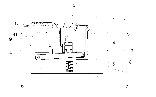
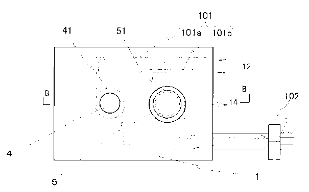
[0044] Embodiment 1: The exhaust device for a die-casting mold provided in this preferred embodiment is as attached figure 1 , attached figure 2 shown, with figure 1 Provided that the fixed module 1 is equipped with the situation of the gas delivery device 10, the appended figure 2 is attached figure 1 A-A sectional view of A-A shows the cross-section of the exhaust device. At the same time attached figure 1 It is the top view of the moving module 2 of the exhaust device after it has been folded off. The symbol 1 shows the fixed module for die-casting, the symbol 2 shows the moving module, and the symbol 3 shows the space between the fixed module 1 and the moving module 2. An exhaust passage formed and communicated with the die-casting mold cavity. Marked 4 is a pressure-receiving plunger located at the intake side 13 of the exhaust passage 3, and the pressure-receiving plunger 4 is arranged on the fixed module 1 and can move up and down.

[0045] Marked 5 is a blo...

Embodiment 2

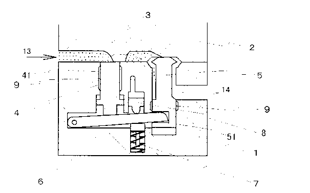
[0047] Embodiment 2: A kind of exhaust device for die-casting mold that this preferred embodiment provides is as attached image 3 , attached Figure 4 As shown, the difference between this preferred embodiment and the first embodiment lies in the formation of the air stagnation portion 9. Obviously, the air stagnation portion 9 may not be formed by cutting the outer circumferences of the pressurized plunger 4 and the lock valve 5 respectively. , but formed by cutting one side of the fixed module 1. Of course, it is also possible to cut the fixed module 1 on one side to form the air stagnation portion 9, and the other side still cuts the outer circumference of the pressure plunger 4 or the lock valve 5 to form the air stagnation portion 9. In this preferred embodiment, the appended Figure 4 The situation shown is that the air retention part 9 on the plunger sliding part 41 on the pressure receiving plunger 4 is formed on the side of the cutting module 1, and the air retentio...


PUM


Abstract

An exhaust device used for a casting die comprises an exhaust passage which is formed between a fixed die and a moving die and is communicated with a casting die cavity. The exhaust device used for the casting die at least comprises: a pressed plunger arranged at an inlet side of the exhaust passage, a holding valve arranged at an outlet side of the exhaust passage, an opening-closing fulcrum bar for transmitting motion of the pressed plunger to the holding valve, an opening device for enabling the holding valve to move towards an open position, and a closing device for pushing the holding valve towards a closing direction through the opening-closing fulcrum bar. An air trapping part is formed on a plunger sliding part of the pressed plunger and a valve sliding part of the holding valve, and a gas transmission device for supplying a pressure gas for the plunger sliding part and the valve sliding part is provided. The present invention solves the problems of low production efficiency and high maintenance cost in the prior art.

Description

technical field [0001] The invention relates to an exhaust device for a die-casting mold, in particular to a kind of gas generated when molten metal enters the die-casting mold cavity and the air in the original cavity is sucked together by a vacuum suction device and discharged from the exhaust passage. Die-casting mold exhaust device. Background technique [0002] Exhaust devices for die-casting molds of the prior art are disclosed in Japanese Patent Application No. 2002-96151 and Japanese Patent Application No. 2002-144008, and its structure is as attached Figure 5 , attached Figure 6 As shown, there is an exhaust passage (3) communicating with the cavity between the fixed module (1) and the moving module (2) of the die-casting mold, and the fixed module (1) is provided with a The pressure plunger (4), located on the outlet side of the exhaust passage (3), is provided with a lock valve (5), and also has an opening and closing rod that transmits the action of the pressu...

Claims


Application Information

Patent Timeline
Patent Type & Authority Applications(China)
IPC IPC(8): B22D17/22
CPCB22D17/2038B22D17/22B22D27/15F01L1/00
Inventor 蔡沅材
Owner JAPAN MOLD TRADE
Why Eureka
Try Eureka