Motor-assisted integrated automobile brake system

An automobile brake system and power-assisted technology, which is applied in the direction of brakes, brake transmissions, vehicle components, etc., can solve the problems of cost increase, volume increase, and safety, and achieve reduced braking distance and high braking strength , the effect of simple structure

Active Publication Date: 2012-11-28
ZHEJIANG ASIA PACIFIC MECHANICAL & ELECTRONICS
View PDF9 Cites 26 Cited by
  • Summary
  • Abstract
  • Description
  • Claims
  • Application Information

AI Technical Summary

Problems solved by technology

Vacuum-assisted braking systems are widely used in traditional fuel vehicles; hydraulic-assisted braking systems use high-pressure accumulators to make the system complex, and require high machining accuracy and control strategies for solenoid valves, which is technically difficult , high production cost, not widely used
With the popularity and promotion of new energy vehicles in recent years, if the traditional vacuum-assisted braking system is adopted, additional vacuum pumps and vacuum tanks will be required, which makes the already complex braking system more complicated, not only increasing the cost, but also Increase in size and decrease in reliability
[0003] The invention patent of "an electric power-assisted braking system" (the application number is 200710111537.5, the publication number is CN 10132778A, and the publication date is December 24, 2008). Security risks

Method used


Image

  • Motor-assisted integrated automobile brake system
  • Motor-assisted integrated automobile brake system
  • Motor-assisted integrated automobile brake system

Examples


Embodiment Construction

[0026] The present invention will be further described below in conjunction with drawings and embodiments.

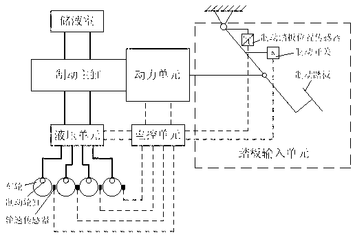
[0027] Such as figure 1 Shown is a schematic diagram of the composition of the motor-assisted integrated vehicle braking system.

[0028] The invention includes a pedal input unit, a power unit, a hydraulic unit, an electric control unit, a brake master cylinder and a liquid storage chamber; the pedal input unit is connected with the power unit, the power unit is connected with the brake master cylinder, and the brake master cylinder is connected with the storage The liquid chamber is connected with the hydraulic unit, the electric control unit is respectively connected with the pedal input unit, the power unit and the circuit of the hydraulic unit, and the hydraulic unit is connected with each brake wheel cylinder.

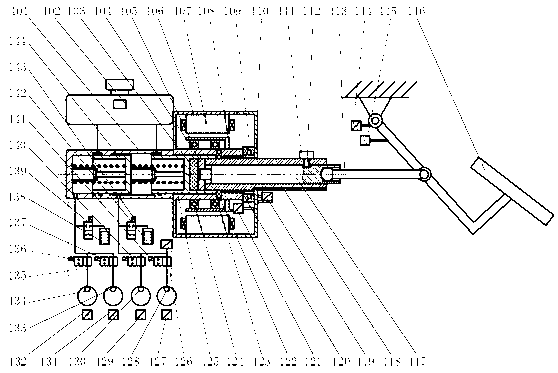
[0029] Such as figure 2 Shown is a schematic diagram of the structure of the motor-assisted integrated vehicle braking system.

[0030] In the pedal i...


PUM


Abstract

The invention discloses a motor-assisted integrated automobile brake system. The motor-assisted integrated automobile brake system comprises a pedal input unit, a power unit, a hydraulic unit, a brake master cylinder, and a liquid storage chamber, wherein the pedal input unit is connected with the power unit; the power unit is connected with the brake master cylinder; the brake master cylinder is respectively connected with the liquid storage chamber and the hydraulic unit; an electric control unit is electrically connected with the pedal input unit, the power unit and the hydraulic unit respectively; and the hydraulic unit is connected with each brake cylinder. According to the invention, a direct current motor drives a ball screw to push the brake master cylinder through a rubber reaction disc to generate assisting power, thereby realizing three braking modes of driver braking, motor braking, and coordinated braking of driver and motor. When the motor fails, the driver can also realize large braking intensity by executing braking independently so as to ensure safe and reliable braking. The motor-assisted integrated automobile brake system disclosed by the invention has the advantages of small size of the overall brake system, light weight and low cost, can integrate a plurality of functions of ABS (anti-lock brake system), TCS (traction control system), ESP (electronic stability program) and the like, and can effectively reduce the braking distance.

Description

technical field [0001] The invention relates to a power-assisted vehicle brake system, in particular to a motor-assisted integrated vehicle brake system. Background technique [0002] Automobile braking system is an extremely important part to ensure driving safety. At present, most automobiles use power-assisted braking system to reduce the driver's pedal force when braking, reduce the driver's driving fatigue, and ensure safe and reliable driving. Traditional power-assisted braking systems mainly adopt two forms: vacuum-assisted and hydraulic-assisted. Vacuum-assisted braking systems are widely used in traditional fuel vehicles; hydraulic-assisted braking systems use high-pressure accumulators to complicate the system structure, require high machining accuracy and control strategies for solenoid valves, and are technically difficult , the production cost is high, and it has not been widely used. In recent years, with the popularization and promotion of new energy vehicle...

Claims


Application Information

Patent Timeline
IPC IPC(8): B60T13/74
Inventor 郭立书杨雄施正堂黄伟中李静
Owner ZHEJIANG ASIA PACIFIC MECHANICAL & ELECTRONICS
Why Eureka
Try Eureka