In-parallel sampling over-current protection circuit
A technology of overcurrent protection circuit and sampling circuit, which is applied in the direction of electrical components, output power conversion devices, etc., can solve the problems of poor consistency, unfavorable mass production, and increased temperature rise of devices, so as to achieve simple and easy circuit and facilitate mass production , the effect of channel current reduction
- Summary
- Abstract
- Description
- Claims
- Application Information
AI Technical Summary
Problems solved by technology
Method used
Image

Examples
Embodiment 1
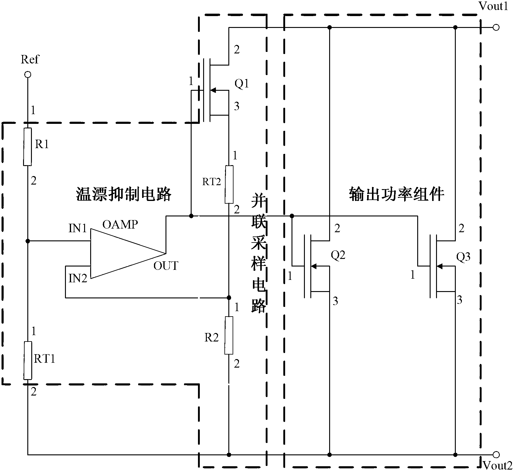
[0033] Such as figure 1 As shown, it is a circuit diagram of the parallel sampling overcurrent protection circuit of the first embodiment of the present invention. This invention is used inside a solid-state relay or a solid-state power controller, specifically including:
[0034] The temperature drift suppression circuit includes: a first resistor R1, a first thermistor RT1, a second resistor R2, a second thermistor RT2 and an operational amplifier OAMP; a parallel sampling circuit includes: a first switching tube Q1, a second thermal The sensitive resistor RT2 and the second resistor R2; the output power assembly is composed of N second switch tubes connected in parallel. In this embodiment, as a preference, N=2 is selected, that is, two second switch tubes are connected in parallel, respectively Q2 and Q3; a reference input terminal Ref, a first output terminal Vout1 and a second output terminal Vout2.
[0035] In the temperature drift suppression circuit, the first termin...
Embodiment 2
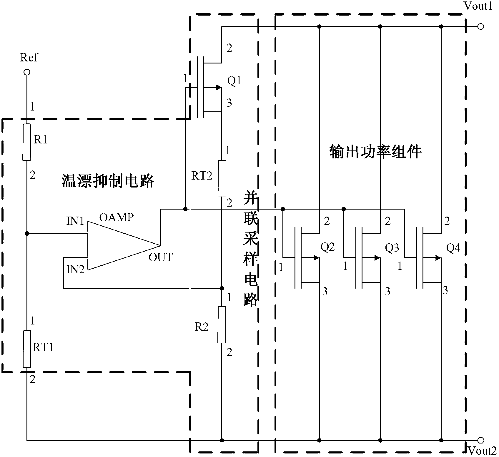
[0044] Such as figure 2 As shown, it is a circuit diagram of a parallel sampling overcurrent protection circuit according to the second embodiment of the present invention. This invention is used inside a solid-state relay or a solid-state power controller, and specifically includes:
[0045] The temperature drift suppression circuit includes: a first resistor R1, a first thermistor RT1, a second resistor R2, a second thermistor RT2 and an operational amplifier OAMP; a parallel sampling circuit includes: a first switching tube Q1, a second thermal The sensitive resistor RT2 and the second resistor R2; the output power component is composed of N second switch tubes connected in parallel. In this embodiment, as a preference, N=3 is selected, that is, three second switch tubes are connected in parallel, which are respectively Q2, Q3 and Q4; reference input terminal Ref, first output terminal Vout1 and second output terminal Vout2.
[0046] In the temperature drift suppression c...
Embodiment 3
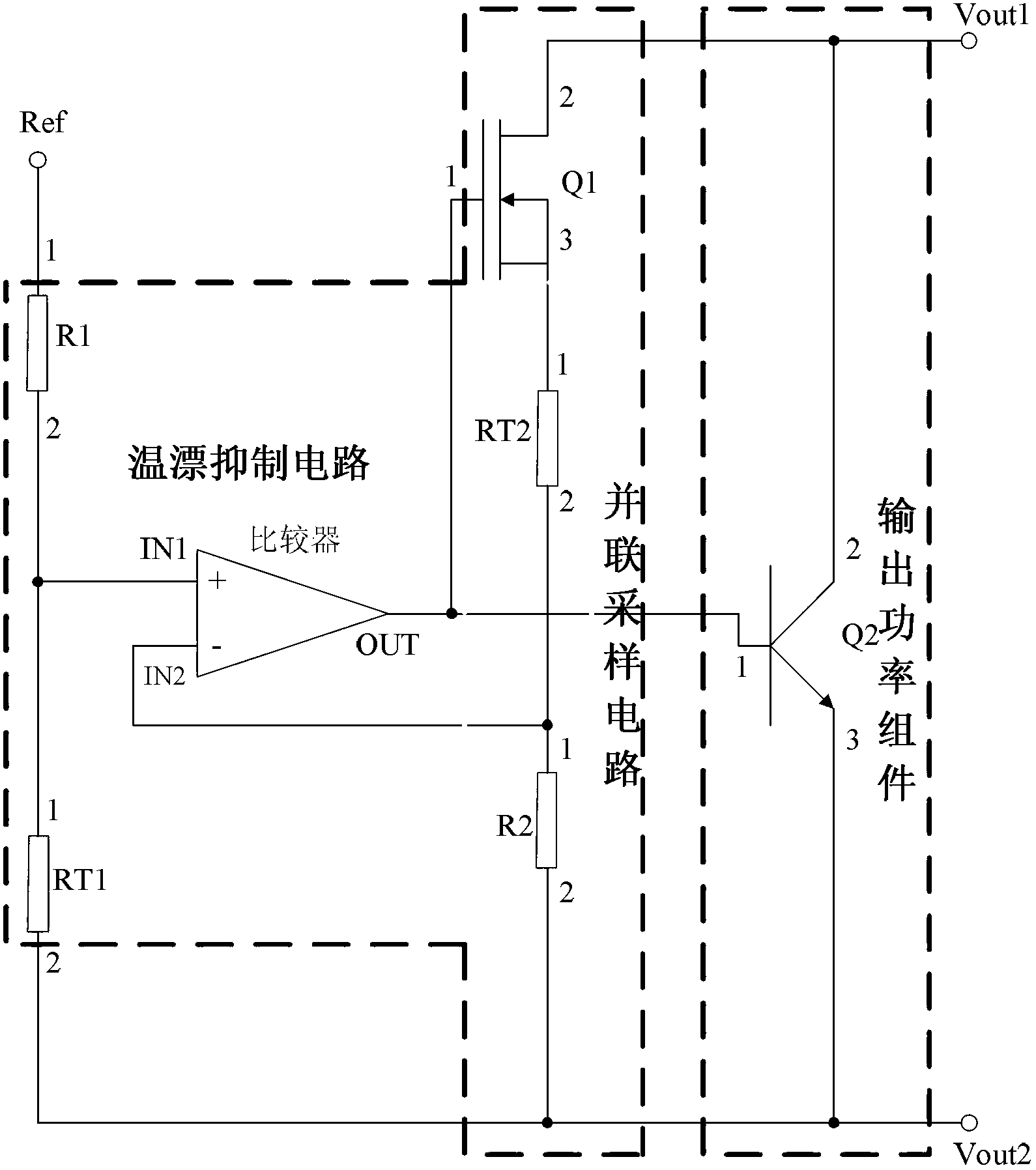
[0055] Such as image 3 As shown, it is a circuit diagram of a parallel sampling overcurrent protection circuit according to the third embodiment of the present invention. This invention is used inside a solid-state relay or a solid-state power controller, and specifically includes:
[0056] The temperature drift suppression circuit includes: the first resistor R1, the first thermistor RT1, the second resistor R2, the second thermistor RT2 and a comparator; the parallel sampling circuit includes: the first switch tube Q1, the second thermistor Resistor RT2 and second resistor R2; the output power component is composed of N second switch tubes connected in parallel. In this embodiment, as a preference, N=1 is selected, that is, one second switch tube Q2; the reference input terminal Ref, the second switch tube Q2 An output terminal Vout1 and a second output terminal Vout2.
[0057] In the temperature drift suppression circuit, the first terminal of the first resistor R1 is con...
PUM
 Abstract
Description
Claims
Application Information
 - Generate Ideas
- Intellectual Property
- Life Sciences
- Materials
- Tech Scout
- Unparalleled Data Quality
- Higher Quality Content
- 60% Fewer Hallucinations
Browse by: Latest US Patents, China's latest patents, Technical Efficacy Thesaurus, Application Domain, Technology Topic, Popular Technical Reports.
© 2025 PatSnap. All rights reserved.Legal|Privacy policy|Modern Slavery Act Transparency Statement|Sitemap|About US| Contact US: help@patsnap.com