Female connector, male connector, connection structure, liquid supply circuit, and medical container
A technology of female connector and male connector, applied in the field of medical containers, can solve problems such as liquid tightness damage, and achieve the effect of cost reduction
- Summary
- Abstract
- Description
- Claims
- Application Information
AI Technical Summary
Problems solved by technology
Method used
Image

Examples
Embodiment approach 1
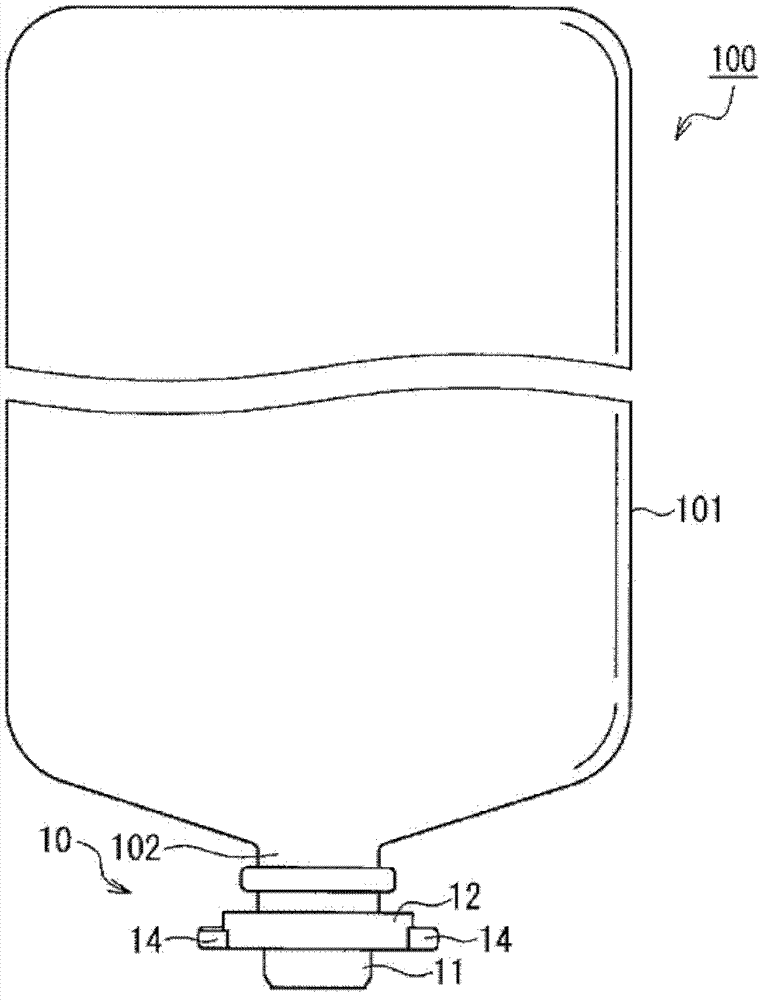
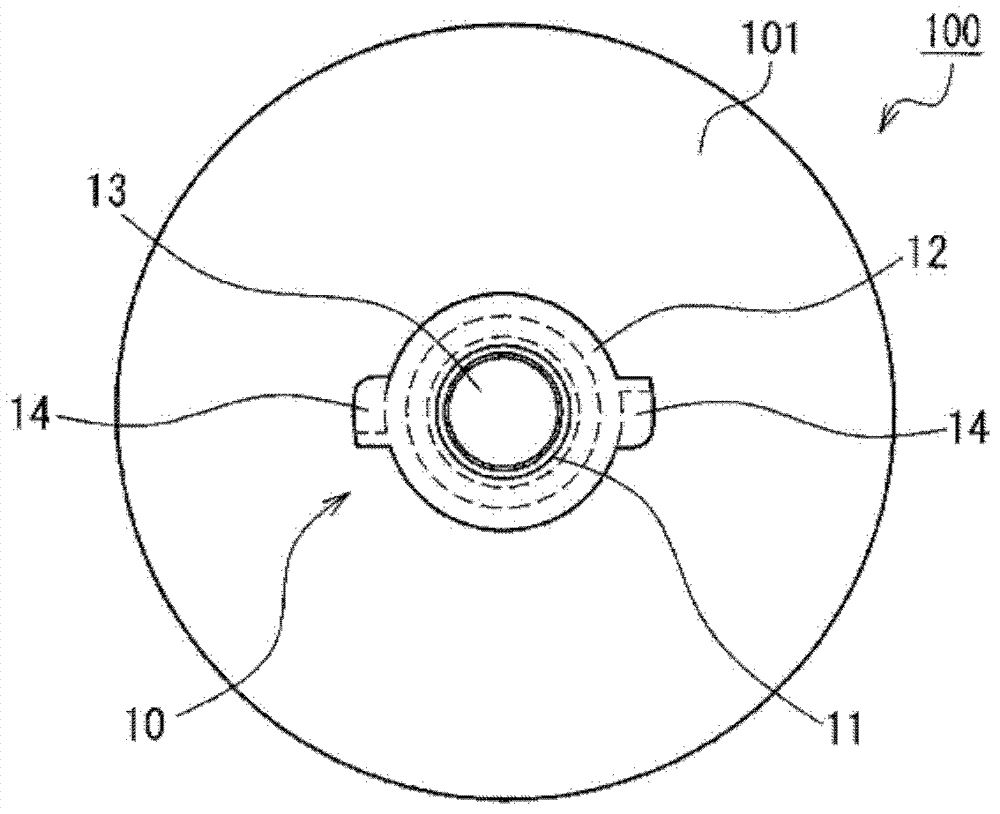
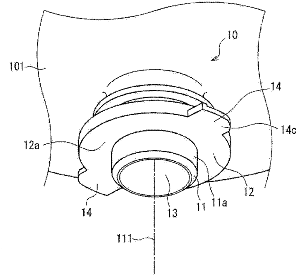
[0156] Figure 1A It shows a schematic structure of an example of a medical container (medical container 100) including an example of a male connector Q (male connector 10) connectable to an example of a female connector A (female connector 15) of the present invention main view, Figure 1B yes Figure 1A Bottom view of the shown medical container. Figure 2A yes Figure 1A Partially enlarged perspective view of the medical container of Figure 2B yes Figure 1A A partially enlarged front view of a medical container, Figure 2C yes Figure 1A Partially enlarged bottom view of the medical container (wherein the main body of the container is omitted). exist Figure 2A , the dashed-dotted line 111 is the central axis of the male connector 10 . Let the direction of the central axis 111 be the up-down direction, and Figure 2A The upper side of the paper (the container main body 101 side of the medical container 100 ) is referred to as "upper side", and the lower side of ...
Embodiment approach 2
[0182] Figure 7A It is a main diagram showing a schematic structure of an example of a medical container (medical container 300) including an example of the male connector P (male connector 30) of the present invention connected to an example of the female connector B (female connector 35). view, Figure 7B yes Figure 7A Bottom view of the shown medical container. Figure 8A yes Figure 7A Partially enlarged perspective view of the medical container of Figure 8B yes Figure 8A A partially enlarged front view of a medical container, Figure 8C yes Figure 7A An enlarged bottom view of a part of the medical container (wherein the main body of the container is omitted). exist Figure 8A , the dashed-dotted line 333 is the central axis of the male connector 30 . Let the direction of the central axis 333 be the up-down direction, and Figure 8A The upper side of the paper (the container main body 301 side of the medical container 300 ) is referred to as "upper side", a...
Embodiment approach 3
[0197] The male connector 10 connected to the female connector 15 described in (Embodiment 1) and an example of the male connector P (male connector 30) described in (Embodiment 2) are each integrally molded. on the port of the medical container. However, these male connectors may also be detachably connected to the ports by means of a connecting mechanism.
[0198] Such as Figure 13 As shown, the male connector 60 as an example of the male connector P of the present invention includes a pedestal 62, a tubular portion 61 protruding downward from the center of one main surface of the pedestal 62, and is arranged on the side opposite to the tubular portion 61 of the pedestal 62. A side cap portion 68 and a pair of engaging claws 64 protrude outward from the outer peripheral surface of the pedestal 62 . The base 62, the tubular portion 61, and the engaging claw 64 may have the same structure as that of the male connector 30 described in (Embodiment 2). On the inner peripheral...
PUM
 Abstract
Description
Claims
Application Information
 - R&D
- Intellectual Property
- Life Sciences
- Materials
- Tech Scout
- Unparalleled Data Quality
- Higher Quality Content
- 60% Fewer Hallucinations
Browse by: Latest US Patents, China's latest patents, Technical Efficacy Thesaurus, Application Domain, Technology Topic, Popular Technical Reports.
© 2025 PatSnap. All rights reserved.Legal|Privacy policy|Modern Slavery Act Transparency Statement|Sitemap|About US| Contact US: help@patsnap.com