Three-phase relative permeability testing method based on CT (computed tomography) scanning

A technology of relative permeability and CT scanning, which is applied in the field of physical simulation test devices for core oil reservoirs to achieve the effects of easy operation, intuitive results and simple structure

Active Publication Date: 2012-12-05
PETROCHINA CO LTD
View PDF4 Cites 15 Cited by
  • Summary
  • Abstract
  • Description
  • Claims
  • Application Information

AI Technical Summary

Problems solved by technology

[0040] However, there is not yet a complete test system to complete the measurement and collection of the above

Method used


Image

  • Three-phase relative permeability testing method based on CT (computed tomography) scanning
  • Three-phase relative permeability testing method based on CT (computed tomography) scanning
  • Three-phase relative permeability testing method based on CT (computed tomography) scanning

Examples


Embodiment 1

[0064] Embodiment 1: Three-phase relative permeability test system based on CT scanning.

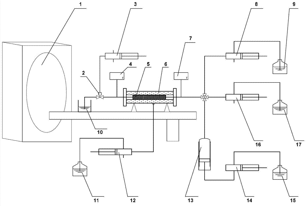
[0065] Please refer to figure 1 , a test system in a preferred embodiment of the present invention includes a CT scanner 1, a core holder 6, a confining pressure system, an injection system and a back pressure control system. The core holder 6 is made of polyether ether ketone resin (PEEK) material, with a maximum pressure resistance of 30MPa and a maximum temperature resistance of 150°C. An inlet pressure gauge 7 is arranged at the inlet of the core holder 6, and an outlet pressure gauge 4 is arranged at the outlet. The inlet end of the core holder 6 is connected to the injection system, and the injection system is composed of an oil injection system, a water injection system and a gas injection system. The oil injection system includes an oil pump 8 and an oil storage container 9 , the water injection system includes a water pump 16 and a water storage container 17 , and the gas inje...

Embodiment 2

[0066] Embodiment 2: Use the device of Embodiment 1 to carry out the three-phase relative permeability test method. Specific steps are as follows:

[0067] 1) The core is loaded into the core holder, and the confining pressure is applied;

[0068] 2) Scan the dry core sample under two scanning voltages, record the scanning position and scanning conditions, and obtain the CT value of the dry core under the two energies;

[0069] 3) After the core is 100% evacuated and saturated with brine, the core is scanned under the same two scanning voltages, scanning conditions and scanning positions as in step 2), and the core CT value of fully saturated brine under two energies is obtained;

[0070] 4) During the displacement experiment, scan the core under the same two scan voltages, scan conditions and scan positions as in step 2), and obtain the CT values ​​of the core under the two energies at that moment;

[0071] 5) Scan the air, experimental brine, experimental oil and experimen...


PUM


Abstract

The invention provides a three-phase relative permeability testing method based on CT (computed tomography) scanning, the method is applied to a three-phase relative permeability testing system based on CT scanning; the system comprises a CT scanner, a rock core holder, a confining pressure system, a filling system and a return pressure control system, wherein the filling system comprises an oil filling system, a water filling system and a gas filling system which are respectively connected with an inlet end of the rock core holder; the method comprises the following steps: an inlet pressure gauge (7) is arranged at the inlet of the rock core holder (6); an outlet pressure gauge (4) is arranged at the outlet of the rock core holder (6); a confining pressure interface of the rock core holder (6) is connected with the confining pressure system; and the outlet end of the rock core holder (6) is connected with the return pressure control system. The system and the method are used for carrying out CT scanning on a whole three-phase displacement process and acquiring the pressure of the inlet and the outlet throughout the whole process so as to obtain fluid saturation data of the whole process; and the system and the method are visual and accurate in result, simple in structure and convenient to operate.

Description

technical field [0001] The invention relates to a physical simulation test device for a core oil reservoir, in particular to a three-phase relative permeability test method based on CT scanning. Background technique [0002] Recent innovations in the field of petroleum production have drawn attention to the study of three-phase relative permeability. Under production conditions such as carbon dioxide injection, burning oil reservoirs, steam flooding, micellar injection, and nitrogen injection, detailed engineering calculations of reservoir performance require Three-phase relative permeability data. [0003] At present, the calculation of three-phase relative permeability mostly adopts mathematical model method, that is, according to the data of two-phase relative permeability, the three-phase relative permeability is calculated by Stone probability model I or II. This method is fast and simple, but it can only calculate the data of one kind of saturation history, and there ...

Claims


Application Information

Patent Timeline
IPC IPC(8): G01N15/08
Inventor 吕伟峰张祖波刘庆杰吴康云严守国罗蔓莉
Owner PETROCHINA CO LTD
Why Eureka
Try Eureka