Spatial light beam compression multichannel imaging optical system with large field of view

A technology of imaging optics and large space, applied in optics, optical components, instruments, etc., can solve problems such as the inability to achieve a large field of view, and achieve the effects of good imaging quality, reduced number, and reduced aperture

Inactive Publication Date: 2012-12-05
BEIJING RES INST OF SPATIAL MECHANICAL & ELECTRICAL TECH
View PDF1 Cites 16 Cited by
  • Summary
  • Abstract
  • Description
  • Claims
  • Application Information

AI Technical Summary

Problems solved by technology

At present, only the CMODIS satellite optical system in China uses a single optical system to achieve multi-spectral ima

Method used


Image

  • Spatial light beam compression multichannel imaging optical system with large field of view
  • Spatial light beam compression multichannel imaging optical system with large field of view
  • Spatial light beam compression multichannel imaging optical system with large field of view

Examples


Example Embodiment

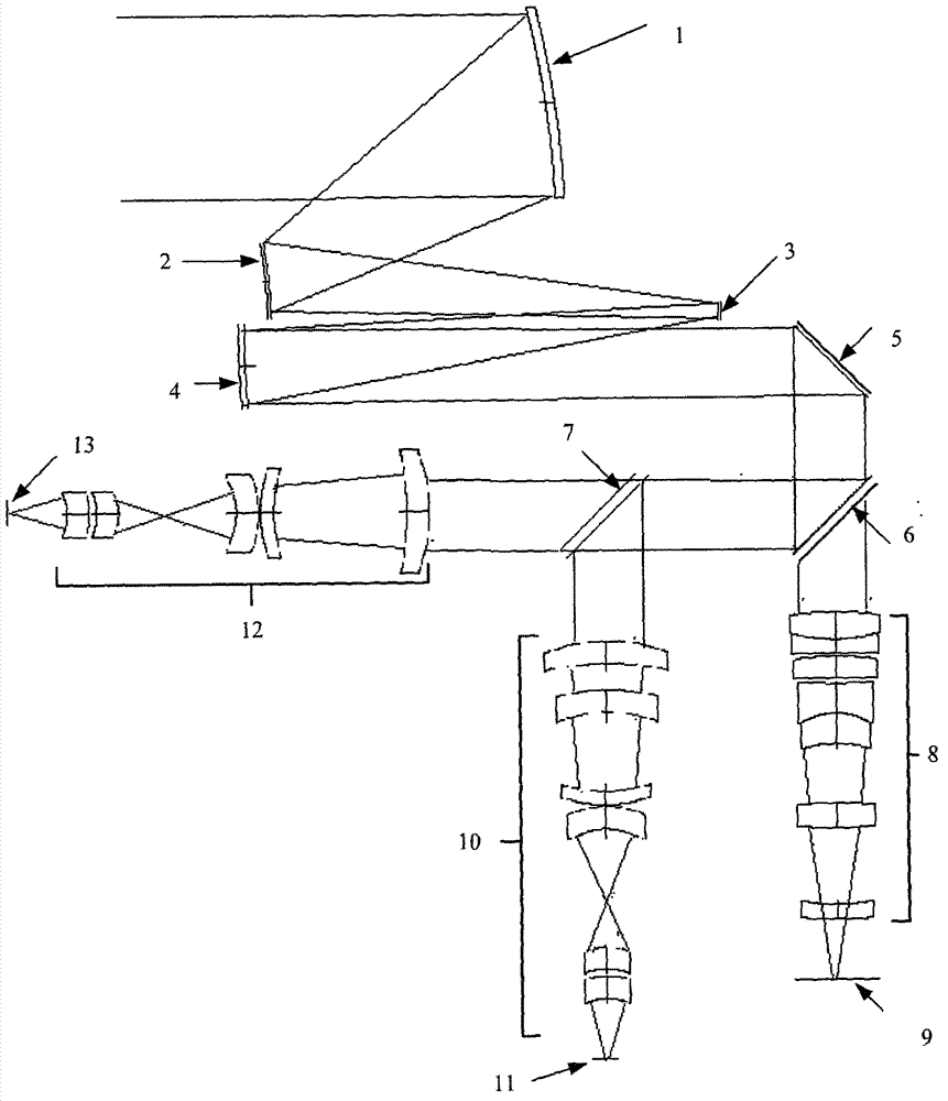
[0026] Such as figure 1 As shown, the optical system of the present invention consists of an off-axis three-reflection compressed beam afocal telephoto system (composed of a primary mirror 1, a secondary mirror 2, a first folding mirror 3, and a third mirror 4), a second folding mirror 5, and visible light near infrared / Infrared spectrum dichroic plate 6, medium wave / long wave spectrum color separation plate 7, visible light and near infrared relay lens group 8, visible light and near infrared focal plane device 9, medium wave infrared relay lens group 10, medium wave The focal plane device 11, the long-wave infrared relay lens group 12, and the long-wave focal plane device 13 are composed. The focal length of the front objective lens (primary lens 1 and secondary lens 2) of the afocal telephoto system is f1, the focal length of the rear objective lens (three lens 4) is f2, and the focal lengths of the three relay lens groups are all f3; then the focal length of the afocal tele...


PUM


Abstract

The invention discloses a spatial light beam compression multichannel imaging optical system with a large field of view. The system comprises an off-axis three-mirror light beam compression afocal telescopic system, a second replicating mirror (5), a first color separation filter (6), a second color separation filter (7), a visible and near infrared relay lens group (8), a visible and near infrared focal plane device (9), a short wave relay lens group (10), a short wave focal plane device (11), a long wave relay lens group (12) and a long wave focal plane device (13), wherein the afocal off-axis three-mirror light beam compression optical system comprises a primary mirror (1), a secondary mirror (2), a first replicating mirror (3) and a third mirror (4). A target radiating light beam is compressed by the afocal off-axis three-mirror light beam compression optical system, emergent parallel light beams pass through the color separation filters and enter following visible and near infrared channel, medium wave channel and long wave infrared channel, and images are formed on focal planes of the channels by the relay lens groups of the channels. The optical system has the advantages that the optical system is large in field of view and relative aperture, wide in spectral range and easy to machine, assemble and adjust, and the like.

Description

technical field [0001] The invention belongs to the technical field of space optical remote sensors, and relates to a visible light / infrared optical imaging system applied to space large field of view, ultra-wide spectrum and multi-channel imaging. Background technique [0002] With the development of remote sensing technology, multispectral imaging remote sensing data has been widely used in resource evaluation, environmental monitoring, disaster early warning and post-disaster assessment, urban planning, target classification and recognition, etc., which has great social and economic benefits. Optical remote sensors need to acquire visible light, near-infrared, medium-wave and long-wave information at the same time. Multiple cameras can be used to image each spectral band separately, or a single camera can be used to achieve multi-channel. [0003] Typical multispectral satellites mainly include the Iandsat series of the United States, the medium resolution imaging spectro...

Claims


Application Information

Patent Timeline
IPC IPC(8): G02B27/10G02B27/00G02B17/06G02B13/18G01J3/28
Inventor 汤天瑾周峰
Owner BEIJING RES INST OF SPATIAL MECHANICAL & ELECTRICAL TECH
Why Eureka
Try Eureka