Speed-self-regulating synchronous generating system

A technology of power generation system and self-speed regulation, applied in the direction of control system, control generator, electrical components, etc., can solve the problems of increased failure rate, large occupied space and high cost

Active Publication Date: 2012-12-05
XIAN DUNAN ELECTRIC
View PDF7 Cites 14 Cited by
  • Summary
  • Abstract
  • Description
  • Claims
  • Application Information

AI Technical Summary

Problems solved by technology

However, for the mechanical output work whose speed changes within a certain range, it cannot satisfy the output power of the synchronous generator with constant frequency and constant voltage.
[0004] In order to make the synchronous generator run at the synchronous speed, a hydraulic coupling or a compound electric drive system is usually used. The hydraulic coupling can smoothly change the transmission speed ratio by adjusting the pressure and flow of the liquid, but when the transmission speed is relatively large , the work efficiency of this type of device is significantly reduced, and the number of mechanical and hydraulic components used in the hydraulic coupler is relatively large, which involves the rotary sealing problem of the high-pressure hydraulic system, is sensitive to materials and working environments, has a short operating life, and relatively maintenance workload Larger; the compound electric drive system is essentially composed of two motors, one of which is used as a generator to convert all or part of the mechanical power of the input shaft into electrical power, and the other motor converts the electrical power into mechanical power. There may be some type of mechanical connection between the two motors to transmit part of the mechanical power to reduce the amount of electric power that needs to be converted. However, the mechanical and electrical structures of the hybrid electric drive system are relatively complicated, large in size, and high in cost. Both are subject to certain restrictions; simple electric drive systems, such as electromagnetic slip clutches, have relatively soft mechanical characteristics, by adjusting the amplitude of its excitation current, the speed of the load can be changed, but similar to the hydraulic When the speed range is large, its work efficiency is significantly reduced
[0005] No matter what method is used, the shaft system composed of the synchronous generator and the speed regulating mechanism in the middle is relatively long. Since at least two sets of connecting mechanisms are required, the space occupied is large and the failure rate increases.

Method used


Image

  • Speed-self-regulating synchronous generating system

Examples


Embodiment Construction

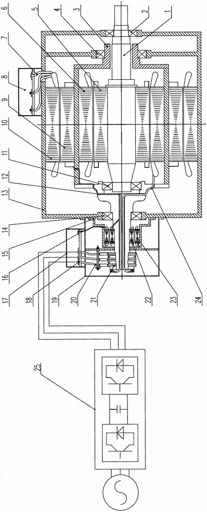
[0020] The system of the present invention integrates the frequency conversion speed regulation electromagnetic torque coupler and the electric excitation synchronous generator design, including the casing 13, the left side of the casing 13 is coaxially connected with the exciter, and the casing 13 is equipped with an electromagnetic torque coupling (not shown) and a synchronous generator (not shown) set on the outside of the electromagnetic torque coupling, the casing 13 includes a left end cover, a right inner end cover and a right outer end cover, and the right outer end cover The first bearing 2 of the inner rotor is arranged on the top, the first bearing of the outer rotor is arranged on the right inner end cover, the second bearing 14 of the outer rotor is arranged on the left end cover, and the electromagnetic torque coupling includes the inner rotor shaft 1 and the outer rotor shaft 3, An inner rotor 5 is fixed on the inner rotor shaft 1. The inner rotor shaft 1 protrud...


PUM


Abstract

The invention relates to a wind power generating technology and discloses a speed-self-regulating synchronous generating system. The speed-self-regulating synchronous generating system is characterized by comprising a shell and an exciter which is coaxially connected with the left side of the shell, wherein an electromagnetic torque coupler and a synchronous generator sleeved on the outer side of the electromagnetic torque coupler are arranged inside the shell; the electromagnetic torque coupler comprises an inner rotor shaft and an outer rotor shaft; an inner rotor is connected onto the inner rotor shaft; an outer rotor is connected onto the inner side of the outer rotor shaft; the synchronous generator comprises a generator rotor and a generator stator; the generator rotor is fixed on the outer side of the outer rotor shaft; and the generator stator is fixed inside the shell. The rotor of the synchronous generator is integrated with the outer rotor of the variable-frequency speed-regulating electromagnetic torque coupler, so that the rotation speed of the rotor of the synchronous generator is a synchronous rotation speed; and the exciting current is changed by regulating input of the synchronous generator exciter so as to ensure that the output voltage and the frequency of the generator are constant.

Description

technical field [0001] The invention relates to wind power generation technology, in particular to a self-adjusting speed synchronous power generation system. Background technique [0002] One of the basic technologies in many application fields such as industrial and agricultural production, energy development, transportation and national defense equipment is transmission technology. In practical applications, it is often necessary to realize stepless speed regulation in the process of power transmission. For example, on the premise that the speed of the input shaft is basically unchanged, it is hoped that the speed of the output shaft of the transmission can be adjusted arbitrarily within a certain range, or conversely when the speed of the input shaft changes within a certain range, the speed of the output shaft can be basically maintained constant. [0003] The speed of the synchronous generator must be at the rated synchronous speed, and the rotor of the synchronous ge...

Claims


Application Information

Patent Timeline
Patent Type & Authority Applications(China)
IPC IPC(8): H02K7/20H02K16/02H02K5/16H02K5/14H02P9/48
Inventor 李俊毅庞卓卉
Owner XIAN DUNAN ELECTRIC
Why Eureka
Try Eureka