Object Positioning With Visual Feedback

An object, positioning system technology, applied in patient positioning for diagnosis, instruments for radiological diagnosis, image data processing, etc., can solve problems such as patient trouble

Active Publication Date: 2012-12-05
C-RAD POSITIONING AB
View PDF5 Cites 23 Cited by
  • Summary
  • Abstract
  • Description
  • Claims
  • Application Information

AI Technical Summary

Problems solved by technology

However, this remote configuration of the display relative to the bed the patient is lying on makes it very cumbersome for medical personnel standing next to the bed and patient to properly reposition the patient while viewing the remote display

Method used


Image

  • Object Positioning With Visual Feedback
  • Object Positioning With Visual Feedback
  • Object Positioning With Visual Feedback

Examples


Embodiment Construction

[0027] Throughout the drawings, the same reference numerals are used for similar or corresponding elements.

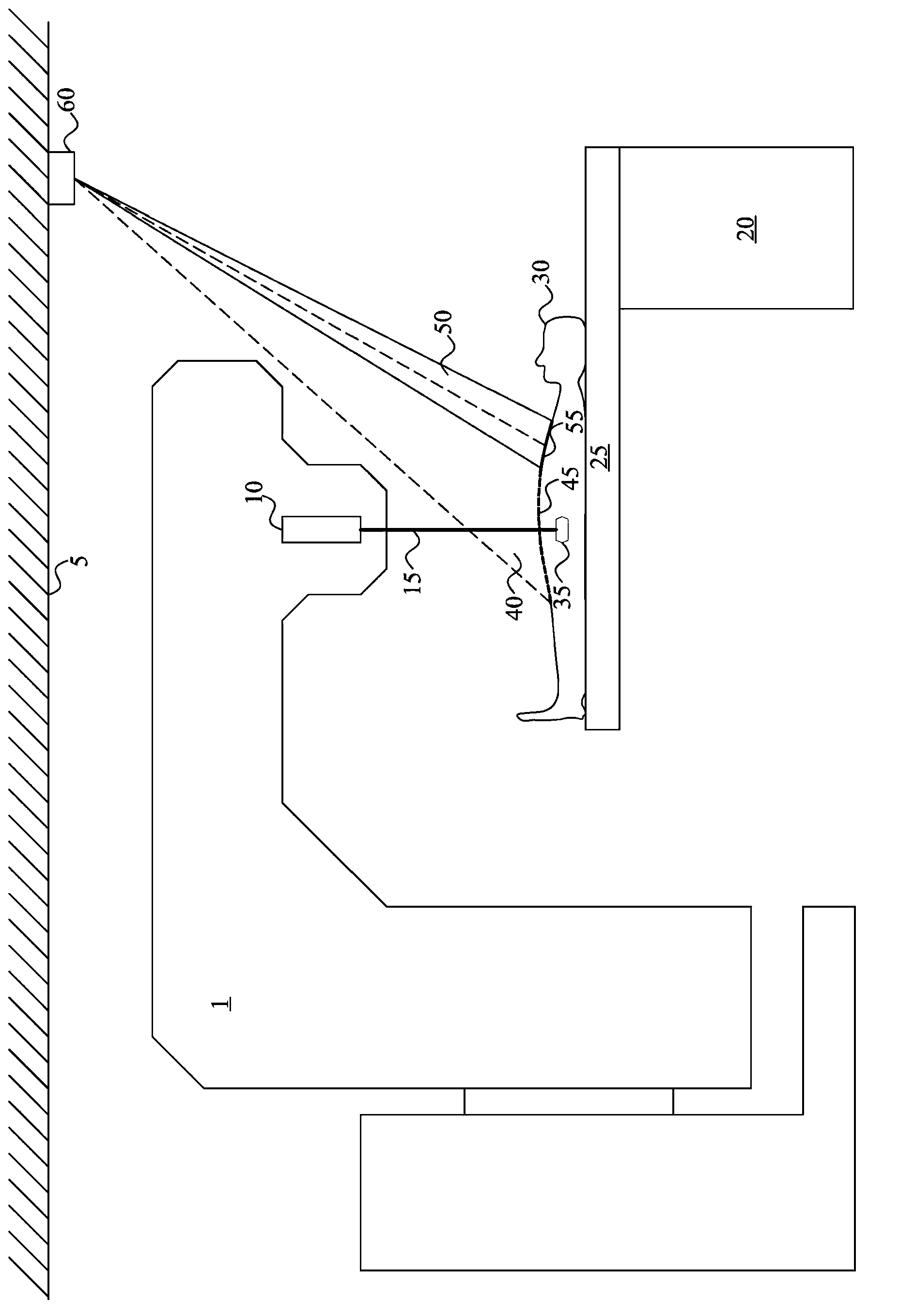
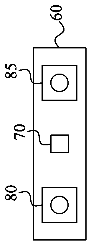
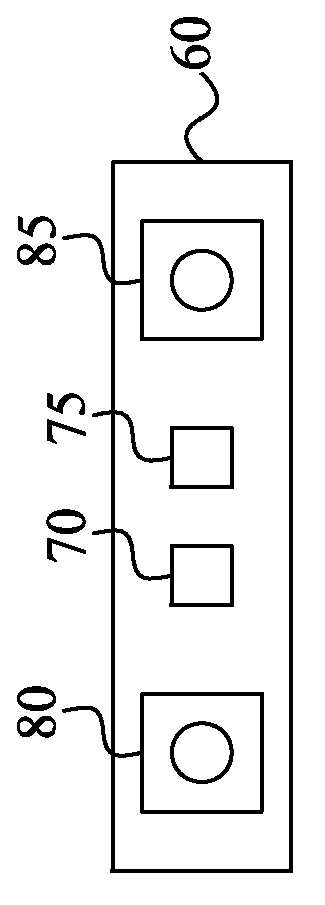
[0028] The embodiments generally relate to a non-contact method and system for determining the position of an object and projecting visual information representing the difference between the determined position and the target position.

[0029] These embodiments are advantageously used in the medical field, and in particular when positioning a patient on a bed, such as an animal patient or a human patient in veterinary applications, for diagnostic imaging, radiation therapy or robotic surgery on the patient. In these applications, the key to effective diagnosis or treatment is the correct positioning of the patient on the bed. In these applications, not only animal patients but also human patients benefit from precise positioning. A common practice is to arrange the different objects close to the patient in bed. For example, immobilization devices may be present on t...


PUM


Abstract

A positioning system comprises a pattern projector (70) for projecting a 2D / 3D pattern (45) onto an object surface. The 2D / 3D pattern (45) is detected by a detector (80, 85), which generates a detection signal that is employed by a pattern analyzing circuit (110) for generating a surface representation of the object surface. A correction analyzing circuit (130) generates a correction signal representative of a discrepancy in position and / or posture of the surface representation relative a stored reference surface representation. The correction signal is employed to generate information (55, 56) that is projected by a light projector (70, 75) onto the object surface. The projected information (55, 56) is indicative of the determined discrepancy in object position and / or posture.

Description

technical field [0001] The present invention relates generally to precise positioning of objects and, in particular, to a system and method for obtaining visual feedback on object positioning. Background technique [0002] There have been considerable developments in the fields of radiation therapy and medical diagnostics over the past few decades. The performance of external beam radiation therapy accelerators, brachytherapy and other specialized radiation therapy equipment has been improving rapidly. Emerging developments in radiation beam quality and adaptation have included new targets and filters, improved accelerators, improved flexibility in beam shaping through new applicators, collimators, and scanning systems, and beam compensation techniques, and have been Improved metrology and geometric treatment verification methods are introduced. [0003] In addition, many powerful 3D diagnostic techniques have been developed, ranging from computed tomography (CT), positron...

Claims


Application Information

Patent Timeline
Patent Type & Authority Applications(China)
IPC IPC(8): A61N5/10A61B19/00A61B6/04
CPCA61N5/00G06T7/004A61N5/1049A61B6/508A61B6/0407G06T2207/30004G06T2207/10028G06T7/0044A61B6/08A61B6/0492A61N2005/1059G06T7/74
Inventor 克里斯托弗·马德
Owner C-RAD POSITIONING AB
Why Eureka
Try Eureka