Dual-pump circulating stirring dispensing process

A pump circulation and dispensing technology, applied in mixer accessories, dissolving, mixer and other directions, can solve the problems of high cost, long mixing time and high energy consumption.

Inactive Publication Date: 2012-12-12
UNIV OF JINAN
View PDF4 Cites 1 Cited by
  • Summary
  • Abstract
  • Description
  • Claims
  • Application Information

AI Technical Summary

Problems solved by technology

[0006] The disadvantages of this kind of motor stirring are: low efficiency, complex structure, high manufacturing precision requirements, high cost, difficult maintenance, high technical level requirements for maintenance workers, long stirring time, large energy consumption, equipment idle rate high
[0007] Application number: 200910039415.9 Chinese patent application for automatic dosing jet mixing and pump stirring sewage treat

Method used


Image

  • Dual-pump circulating stirring dispensing process
  • Dual-pump circulating stirring dispensing process
  • Dual-pump circulating stirring dispensing process

Examples


Embodiment 1

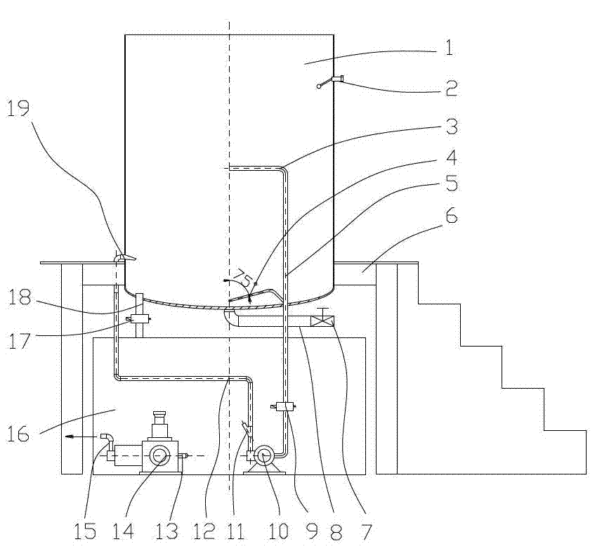
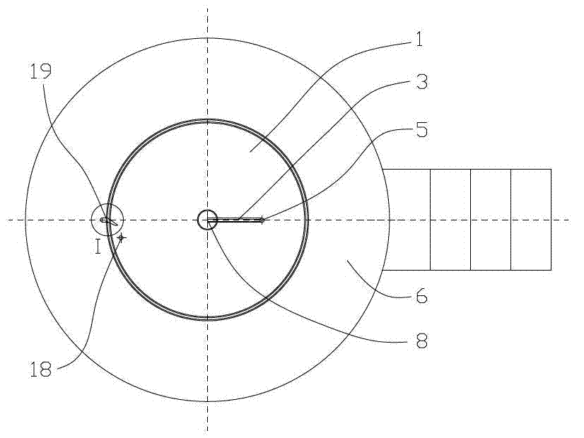
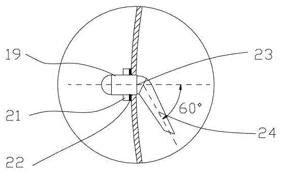
[0043] The double-port parallel pump circulation stirring dispensing process includes: dispensing tank 1, liquid level sensor 2, upper suction pipe 3, lower suction pipe 4, plastic pump suction pipe 5, workbench 6, emptying valve 7, emptying pipe 8, electromagnetic Valve A9, plastic pump 10, check valve 11, stirring pipe 12, discharge pipe 13 of liquid medicine storage tank, metering pump 14, outlet pipe 15 of metering pump, liquid medicine storage tank 16, solenoid valve B17, liquid medicine delivery pipe 18 , agitating nozzle 19, tightening screw nut 21, tightening washer 22, agitating nozzle inlet pipe 23, agitating nozzle outlet pipe 24, taper pipe thread 25, ordinary fine thread 26, upper suction pipe 3 nozzles and lower suction pipe 4 The nozzle is placed in the center of the dispensing tank 1, the upper suction pipe 3 and the lower suction pipe 4 are connected to the suction pipe 5 of the plastic pump, the suction pipe 5 of the plastic pump is connected to the inlet of t...

Embodiment 2

[0062] The double-port parallel pump circulation stirring dispensing process includes: dispensing tank 1, liquid level sensor 2, upper suction pipe 3, lower suction pipe 4, plastic pump suction pipe 5, workbench 6, emptying valve 7, emptying pipe 8, electromagnetic Valve A9, plastic pump 10, check valve 11, stirring pipe 12, liquid medicine storage tank outlet pipe 13, metering pump 14, metering pump outlet pipe 15, medicine liquid storage tank 16, solenoid valve B17, medicine liquid delivery pipe 18 , agitating nozzle 19, tightening screw nut 21, tightening washer 22, agitating nozzle inlet pipe 23, agitating nozzle outlet pipe 24, taper pipe thread 25, ordinary fine thread 26, upper suction pipe 3 nozzles and lower suction pipe 4 The nozzle is placed in the center of the dispensing tank 1, the upper suction pipe 3 and the lower suction pipe 4 are connected to the suction pipe 5 of the plastic pump, the suction pipe 5 of the plastic pump is connected to the inlet of the plasti...


PUM


Abstract

The invention discloses a dual-pump circulating stirring dispensing process and belongs to the field of dispensing in sewage treatment. The dual-pump circulating stirring dispensing process is characterized by including the steps that tap water and coagulants used for sewage treatment are simultaneously added into a dispensing tank, and water is added and stopped until the water level is leveled to a level sensor; an electromagnetic valve A is opened, a plastic pump is started, supernatant in the dispensing tank enters an upper suction pipe, solid particles at the bottom of the dispensing tank are sucked into a lower suction pipe, fluid in the upper suction pipe and in the lower suction pipe enters the dispensing tank together by passing through a plastic pump suction pipe, the plastic pump, a stirring pipe and a stirring nozzle, and circulating fluid enters the dispensing tank to enable the fluid in the tank to rotate so as to stir the coagulants; after the coagulants are dissolved sufficiently, the electromagnetic valve A is closed, and an electromagnetic valve B is opened to enable chemical liquor to enter a chemical liquor storage tank for standby; and when a required unit of sewage treatment facilities needs the chemical liquor, a metering pump is started, and the chemical liquor is delivered to the required unit of the sewage treatment facilities through a metering pump outlet pipe. The dual-pump circulating stirring dispensing process has the advantages of less equipment investment, simple structure, less proneness to blockage, pump overload prevention and easiness in maintenance and replacement.

Description

technical field [0001] The double-port parallel pump circulation stirring dispensing process of the present invention relates to the technical field of pump circulation stirring medicine dispensing. Background technique [0002] The mixing and dispensing method of the agitator driven by the variable speed of the motor that is generally sold on the market and is being used in general sewage stations. [0003] The mixing form is mainly composed of a stirring motor, a high transmission ratio reducer, a mixing blade, a dispensing tank, a support stand, etc. The high transmission ratio reducer generally adopts a cycloidal pinwheel reducer, which has a complex structure and high manufacturing precision requirements , high cost, difficult maintenance, and high technical requirements for maintenance workers. Generally, when this kind of reducer fails, it will be replaced with a new one, resulting in high maintenance and repair costs. [0004] For a long time, the rated power of the...

Claims


Application Information

Patent Timeline
IPC IPC(8): B01F13/10B01F5/10B01F15/00
Inventor 马晶高红鹰于明
Owner UNIV OF JINAN
Why Eureka
Try Eureka