Slotting unit of anode carbon block

A technology of anode carbon block and unit, which is applied in the direction of stone processing tools, manufacturing tools, stone processing equipment, etc., can solve the problems of inability to work continuously, low work efficiency, etc., achieve efficient cutting of exhaust grooves, low production cost, and excellent structure simple effect

Inactive Publication Date: 2012-12-12
陈玉瑞
View PDF11 Cites 18 Cited by
  • Summary
  • Abstract
  • Description
  • Claims
  • Application Information

AI Technical Summary

Problems solved by technology

[0011] The purpose of the present invention is to provide an anode carbon block slotting unit to overcome the shortcomings of the existing anode carbon block exhaust groove cutting equipme...

Method used


Image

  • Slotting unit of anode carbon block
  • Slotting unit of anode carbon block
  • Slotting unit of anode carbon block

Examples


Embodiment 1

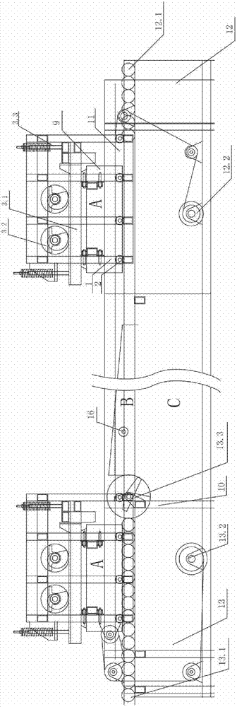
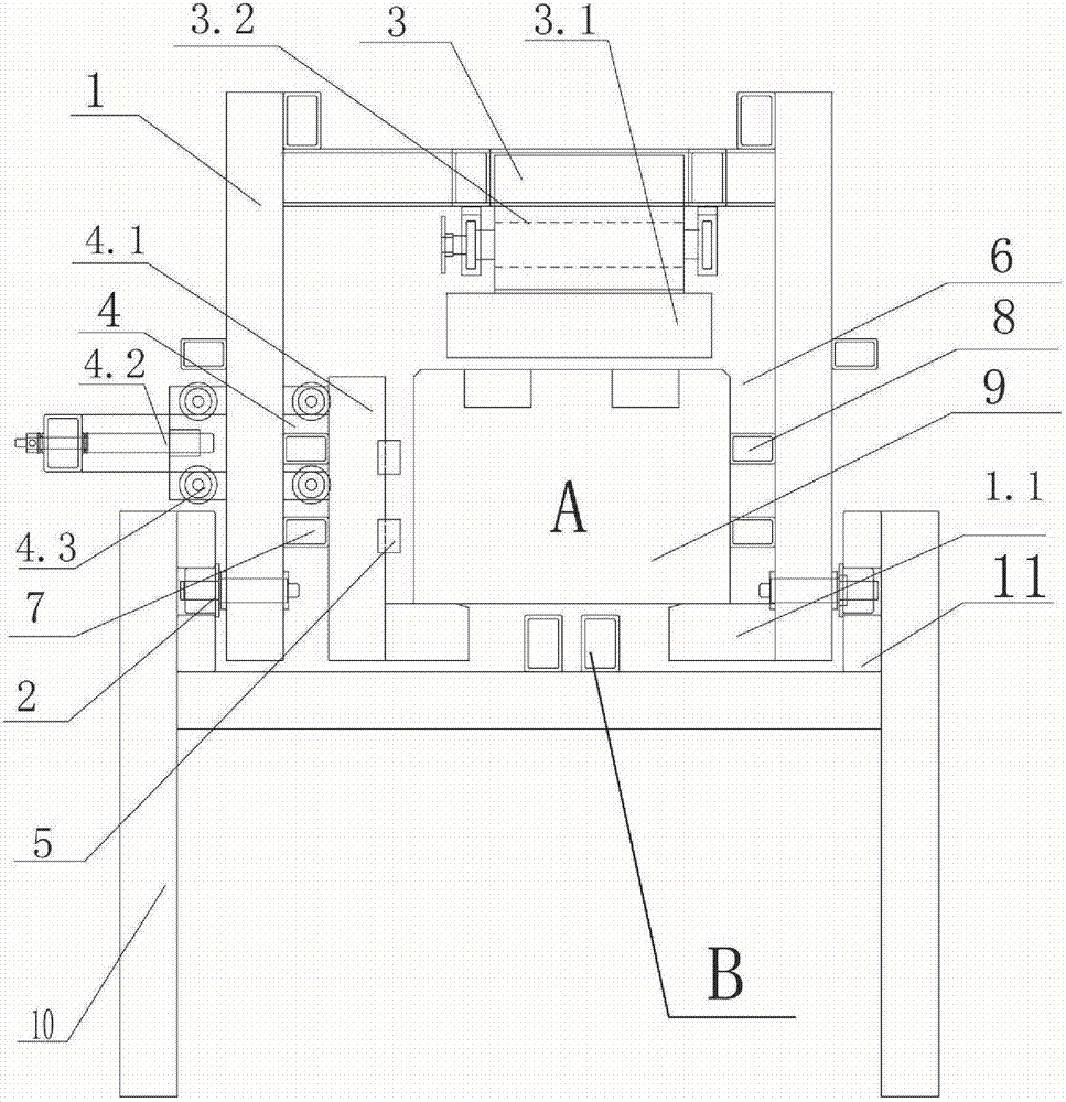
[0039] like Figure 1-4 As shown, the anode carbon block grooving unit includes three parts, the mobile trolley A, the grooving saw blade B and the cutting frame C,

[0040] The mobile trolley A includes a frame 1 and a motor. The frame 1 includes a support frame 1.1 at the bottom. The bottom of the frame 1 is provided with a track wheel 2. The upper part of the frame 1 is provided with an upper pressing device 3. The upper pressing device 3 includes an upper pressing device. Tightening plate 3.1, upper cam 3.2 and return spring A3.3, upper cam 3.2 is set on the top position of pressing plate 3.1, one end of connecting rod in returning spring A3.3 is connected with upper pressing plate 3.1, and the other end is connected with the vehicle The top of the frame 1 is connected; the side pressing device 4 includes an L-shaped side pressing plate 4.1, a side mechanical pull rod 4.2 and a return spring B4.3, and the end of the side mechanical pull rod 4.2 is connected with the side pre...

Embodiment 2

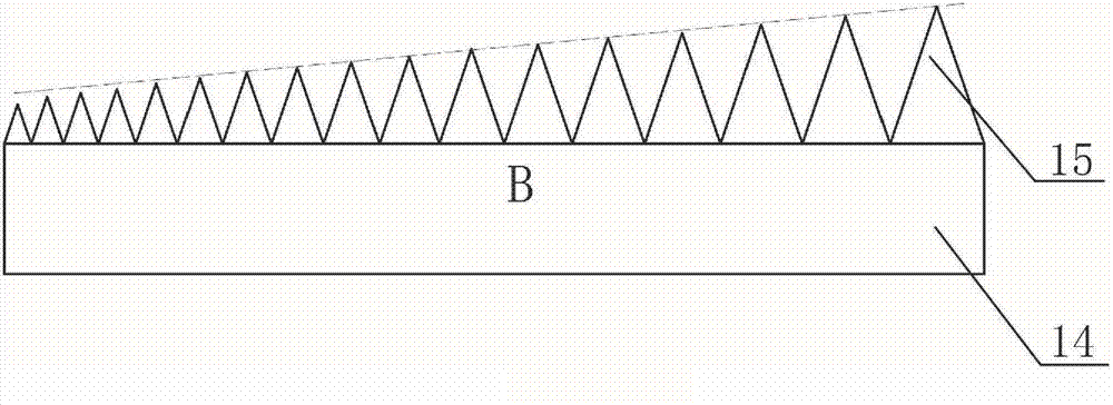
[0045] The difference from Embodiment 1 is that the rear part of the upper pressing plate 3.1 is also provided with a tailgate 3.4, the upper cam 3.2 is replaced by a hydraulic push rod, the side mechanical pull rod 4.2 is also replaced by a hydraulic push rod, and the saw blade mechanical push rod 16 is replaced Forming a hydraulic push rod, the angle between the straight line formed by the top of the sawtooth and the base of the saw blade is 3 degrees, and the other working principles are the same as in Embodiment 1.

Embodiment 3

[0047] The difference from Embodiment 1 is that the upper cam 3.2 is replaced by a mechanical push rod, and the side mechanical pull rod 4.2 is replaced by a cam. The straight line formed by the top of the sawtooth and the saw blade base form an included angle of 5 degrees. Other working principles are the same as in Embodiment 1. .


PUM


Abstract

The invention discloses a slotting unit of an anode carbon block, comprising a motor, a frame (1) and a rack (10). The slotting unit of the anode carbon block is characterized by further comprising a movable vehicle (A), a slotting saw blade (B) and a cutting bracket (C). The bottom of the frame (1) of the movable vehicle is provided with a rail wheel (2), the upper part of the frame (1) is provided with an upper compression device (3), and the lateral part of the frame (1) is provided with a lateral compression device (4). The upper compression device (3) comprises an upper compression plate (3.1) and an upper compression device; and the upper compression device is arranged at the top of the upper compression plate (3.1). The lateral compression device (4) comprises a lateral compression plate (4.1) and a lateral compression device; the lateral compression plate (4.1) is in an L shape; and the lateral compression device is arranged on the lateral part of the lateral compression plate (4.1). The slotting unit of the anode carbon block is simple in structure and low in manufacturing cost, and can effectively compress the anode carbon block and drag the anode carbon block to move so as to realize the slotting work to the anode carbon block.

Description

technical field [0001] The invention relates to an anode carbon block slotting tool for aluminum smelting, in particular to an anode carbon block slotting unit. Background technique [0002] In the aluminum smelting industry, the anode carbon block is used as the anode of the electrolytic cell. The current anode carbon block for electrolytic aluminum production generally uses petroleum coke and pitch coke as the aggregate, and coal tar pitch as the binder. After calcination, crushing, It is made after batching, kneading, shaping and roasting, so it has a hard texture. [0003] The bottom surface of the earliest produced anode carbon block is flat. Later, people found in the process of electrolytic aluminum that the anode carbon block with a flat bottom surface has a slower heating rate and has a larger anode bottom gas film resistance, which makes the electric energy The consumption increases, and at the same time, the bottom of the anode carbon block is easily burned due t...

Claims


Application Information

Patent Timeline
IPC IPC(8): B28D1/06
Inventor 陈玉瑞林国友黄景明罗永城
Owner 陈玉瑞
Why Eureka
Try Eureka