Glue-spray type wireless glue binding machine

A wireless glue binding machine and glue-spraying technology, applied in bookbinding, binding adhesives, printing, etc., can solve problems such as uneven glue layer thickness, long melting time, and difficult control of glue temperature. Good bonding performance, short melting time, and high-quality adhesive binding

Active Publication Date: 2014-09-17
浙江大祥办公设备有限公司
View PDF7 Cites 11 Cited by
  • Summary
  • Abstract
  • Description
  • Claims
  • Application Information

AI Technical Summary

Problems solved by technology

[0004] 1. Due to the opening of the glue tank, the hot melt glue in the glue tank is continuously volatilized, which not only wastes the glue, but also pollutes the working environment;
[0005] 2. The hot melt adhesive in the glue tank has repeatedly experienced the process of heating, cooling, and carbonization, and it will always be a recycled glue liquid. If it is used repeatedly, the bonding performance of the hot melt adhesive will be greatly reduced;
[0006] 3. Every time it is turned on and used, all the solidified hot melt adhesive must be melted before sizing, the melting time is long, and the glue temperature is not easy to control;
[0007] 4. The hot-melt adhesive is applied to the lower side of the stack through the rubber wheel. Because there is no pressure during coating, the bonding between the hot-melt adhesive and the paper fiber is not sufficient. Even if the milling cutter mechanism makes grooves on the lower side of the stack, The hot melt adhesive will be properly squeezed into the groove, but due to the small pressure, the bonding between the hot melt adhesive and the paper fibers is not sufficient. When wrapping thick books and coated paper books, pages often appear, and the back of the book cracks, etc.;
[0008] 5. Since the side glue is formed by the extrusion of side rubber wheels, the thickness of the glue layer is uneven, and the edge is uneven, which affects the quality of the glue binding of the cover

Method used


Image

  • Glue-spray type wireless glue binding machine
  • Glue-spray type wireless glue binding machine
  • Glue-spray type wireless glue binding machine

Examples


Embodiment Construction

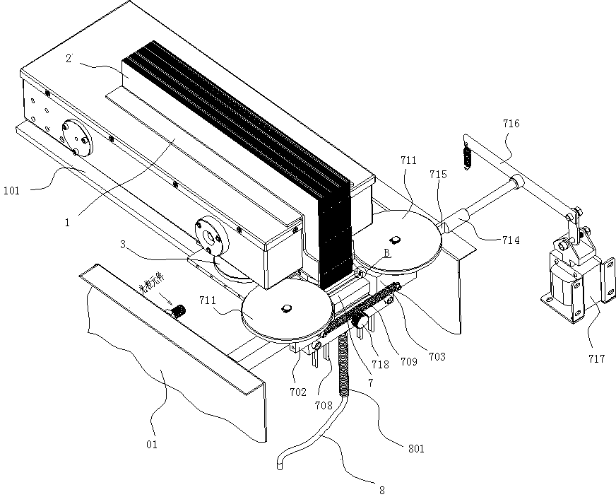
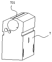
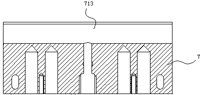
[0027] Such as Figures 1 to 8 As shown, a glue-spraying wireless adhesive binding machine of the present invention includes a frame 01, a sheet stack clamping mechanism 1 arranged on the frame 01, a milling cutter mechanism 3 for milling a notch on the lower side of the sheet stack 2, and gluing mechanism, a cover mechanism, and a control device for controlling the action of the above-mentioned mechanism. The gluing mechanism includes: a nozzle 7, a vertically arranged cylindrical glue tank 9, the top of the nozzle 7 is an inline spray slit 701, and the inline spray slit 701 is arranged along the left and right direction and is located on the page At the front and bottom of the lower side of the stack 2, by adjusting the height of the reference platform 101 of the stack clamping mechanism 1, the distance between the lower side of the stack 2 and the in-line spray slit 701 can be controlled, thereby controlling the glue spraying thickness of the adhesive , the nozzle 7 is pro...


PUM


Abstract

The invention discloses a glue-spray type wireless glue binding machine, comprising a rack, a page fold clamping mechanism, a milling cutter mechanism, a gluing mechanism, a cover installing mechanism, and a control device, wherein the gluing mechanism comprises a spray nozzle, a glue tank, and a heating component, a linear spray slit is arranged on the top of the spray nozzle, the linear spray slit is communicated with a glue outlet at the bottom of the glue tank through a glue solution control valve and a glue transmission tube sequentially, the linear spray slit is provided with a left spray nozzle slide block and a right spray nozzle slide block which are close to each other by virtue of the pulling of a reset spring, in the form of being capable of sliding to the left and the right, and guide wheels are arranged on the tops of both of the left spray nozzle slide block and the right spray nozzle slide block. According to the glue-spray type wireless glue binding machine disclosed by the invention, the melted glue water is sprayed to page fold sides, and the glue solution is adequately bonded with paper fibres, so that the binding performance is good and the glue binding quality is high; moreover, the defects of repeated heating and using of the glue solution are overcome, pollution is avoided, glue binding for complete books or texts is ensured, and the phenomena of page missing, book back cracking and the like are prevented; and the two adjacent pages can be flatly spread with 180 degrees, thus facilitating reading, copying or scanning, which is another revolution for wireless glue binding for books or texts.

Description

technical field [0001] The invention relates to a wireless glue binding device for books, in particular to a glue spraying type wireless glue binding machine. Background technique [0002] Existing wireless glue binding machines, such as Figure 9 As shown, it mainly includes a frame, a stack clamping mechanism 1 arranged on the frame, and a gap milling slot for the lower side of the stack 2 (also called the back) is provided at the front and lower side of the stack clamping mechanism 1. Milling cutter mechanism 3, in the front of said milling cutter mechanism 3, there is a sizing mechanism for coating the back glue on the lower side of the page stack 2 and coating side glue on both sides of the lower end of the page stack 2, a cover mechanism, and a As for the control device that controls the action of the above mechanism, the gluing mechanism includes a glue tank 4, a back rubber wheel 5 and a side rubber wheel 6. After the page stack clamping mechanism 1 clamps the binder...

Claims


Application Information

Patent Timeline
Patent Type & Authority Patents(China)
IPC IPC(8): B42C9/00B42C19/00
Inventor 黄力树黄峥嵘
Owner 浙江大祥办公设备有限公司
Why Eureka
Try Eureka