Spray nozzle mechanism of glue-spray type wireless glue binding machine

A wireless glue binding machine and glue spraying technology, which is applied in the direction of spraying devices, spraying devices, and adhesives for binding, etc., can solve the problem of insufficient bonding between hot melt adhesives and paper fibers, affecting the quality of cover binding, and the height of edges unevenness and other problems, to achieve the effect of improving the quality of glue binding, simple structure and sufficient bonding

Active Publication Date: 2014-09-24
浙江大祥办公设备有限公司
View PDF9 Cites 0 Cited by
  • Summary
  • Abstract
  • Description
  • Claims
  • Application Information

AI Technical Summary

Problems solved by technology

[0004] 1. The hot melt adhesive is applied to the lower side of the stack through the rubber wheel. Because there is no pressure during coating, the bonding between the hot melt adhesive and the paper fiber is not sufficient. Even if the milling cutter mechanism slots the lower side of the stack, The hot melt adhesive will be properly squeezed into the groove, but due to the small pressure, the bonding between the hot melt adhesive and the paper fibers is not sufficient. When wrapping thick books and coated paper books, pages often appear, and the back of the book cracks, etc.;
[0005] 2. Since the side glue is formed by the extrusion of side rubber wheels, the thickness of the glue layer is uneven, and the edges are uneven, which affects the quality of the glue binding of the cover

Method used


Image

  • Spray nozzle mechanism of glue-spray type wireless glue binding machine
  • Spray nozzle mechanism of glue-spray type wireless glue binding machine
  • Spray nozzle mechanism of glue-spray type wireless glue binding machine

Examples


Embodiment Construction

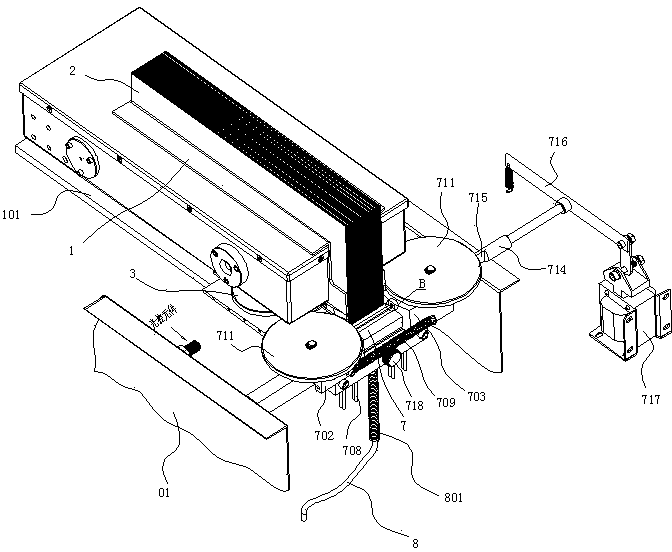
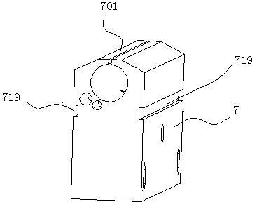
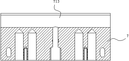
[0030] Such as Figures 1 to 9As shown, the nozzle mechanism of a glue-spraying wireless adhesive machine of the present invention includes a nozzle 7, and the top of the nozzle 7 is a straight spray slit 701, and a glue control valve is arranged in the nozzle 7 to control the flow into the glue. Describe the on-off of the hot-melt glue liquid of in-line spray slit 701, described glue control valve is opened in the circular through-hole 713 of in-line spray slit 701 lower ends and is installed in this circular through-hole 713 The rotating shaft 714 is formed, and the rotating shaft 714 and the circular through hole 713 are rotatably and sealingly matched, and the middle section of the rotating shaft 714 is provided with a cutout 715 ( figure 1 The slit 715 is shown. After the actual assembly, the slit 715 is located in the middle of the circular through hole 713 and cannot be seen), the width of the slit 715 is smaller than the diameter of the rotating shaft 714, and the len...


PUM


Abstract

The invention discloses a spray nozzle mechanism of a glue-spray type wireless glue binding machine, comprising a spray nozzle, wherein the top of the spray nozzle is a linear spray slit, in which a glue solution control valve is arranged, the glue solution control valve is connected with the glue outlet of a pressure glue tank by virtue of a glue transmission tube through the glue inlet of the spray nozzle, and a spray nozzle heating component is arranged in the spray nozzle; and the spray nozzle mechanism further comprises a left spray nozzle slide block and a right spray nozzle slide block which slide along the linear spray slit, convex edges and guide wheels which are hermetically matched with the linear spray slit are arranged on both of the left spray nozzle slide block and the right spray nozzle slide block, and the left spray nozzle slide block and the right spray nozzle slide block are close to each other in parallel via a reset spring. The spray nozzle mechanism disclosed by the invention can be used for spraying the melted glue solution to the page fold sides which are to be subjected to glue binding under the action of a pressure, and the glue solution is adequately bonded with paper fibres, so that the binding performance is good and the glue binding quality is high; moreover, the defect of repeated heating and using for the glue solution is overcome, pollution is avoided, glue binding for complete books or texts is ensured, and the phenomena of page missing, book back cracking and the like are prevented; and the two adjacent pages can be flatly spread with 180 degrees, thus facilitating reading, copying or scanning, which is another revolution for wireless glue binding for books or texts.

Description

technical field [0001] The invention relates to a wireless gluer for books, in particular to a nozzle mechanism of a glue spraying type wireless gluer. Background technique [0002] Existing wireless glue binding machines, such as Figure 10 As shown, it mainly includes a frame, a stack clamping mechanism 1 arranged on the frame, and a gap milling slot for the lower side of the stack 2 (also called the back) is provided at the front and lower side of the stack clamping mechanism 1. Milling cutter mechanism 3, in the front of said milling cutter mechanism 3, there is a sizing mechanism for coating the back glue on the lower side of the page stack 2 and coating side glue on both sides of the lower end of the page stack 2, a cover mechanism, and a As for the control device that controls the action of the above mechanism, the gluing mechanism includes a glue tank 4, a back rubber wheel 5 and a side rubber wheel 6. After the page stack clamping mechanism 1 clamps the binder to be...

Claims


Application Information

Patent Timeline
Patent Type & Authority Patents(China)
IPC IPC(8): B42C9/00B42C19/00B05B1/02B05B1/30B05B1/24
Inventor 黄力树黄峥嵘
Owner 浙江大祥办公设备有限公司
Why Eureka
Try Eureka