Residuum hydrotreatment-catalytic cracking combination technology

A technology for catalytic cracking and residual oil hydrogenation, which is applied in hydrotreating process, petroleum industry, processing of hydrocarbon oil, etc., can solve problems such as inconvenient adjustment of oil properties, reduce the amount of cold hydrogen used, and achieve flexible combination methods. Improve fluid flow

Active Publication Date: 2012-12-12
PETROCHINA CO LTD
View PDF7 Cites 11 Cited by
  • Summary
  • Abstract
  • Description
  • Claims
  • Application Information

AI Technical Summary

Problems solved by technology

[0007] In the above combined methods, the re-refined oil enters the residual oil hydrotreating unit together with the raw material r

Method used


Image

  • Residuum hydrotreatment-catalytic cracking combination technology
  • Residuum hydrotreatment-catalytic cracking combination technology
  • Residuum hydrotreatment-catalytic cracking combination technology

Examples


Embodiment 1

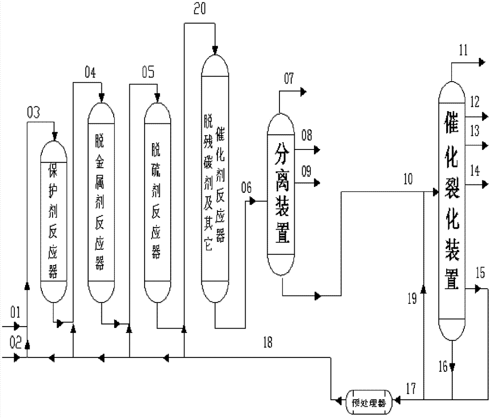
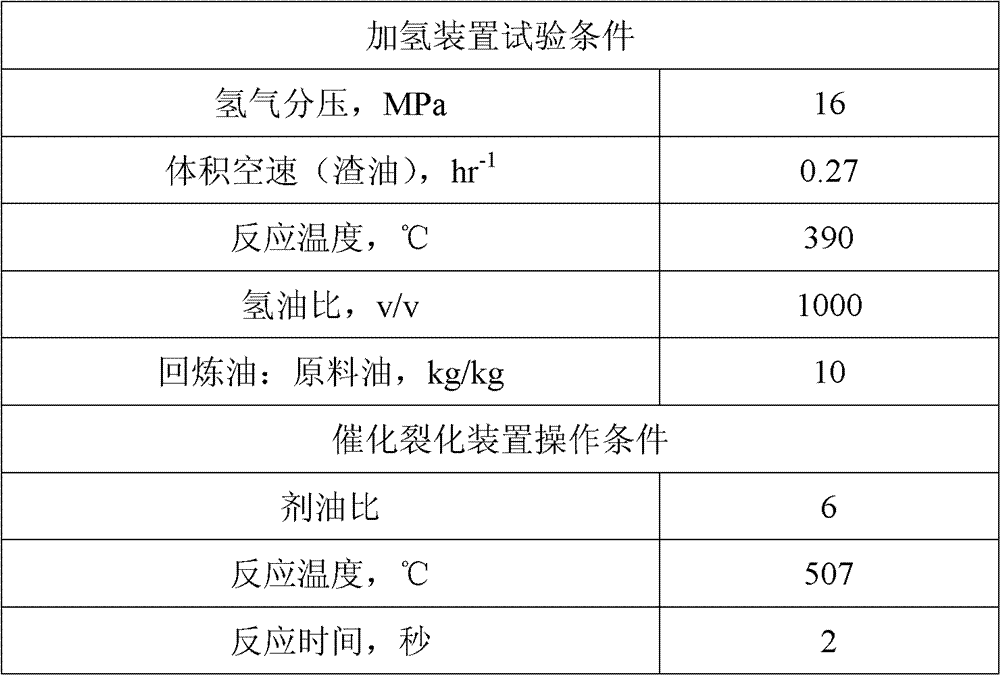
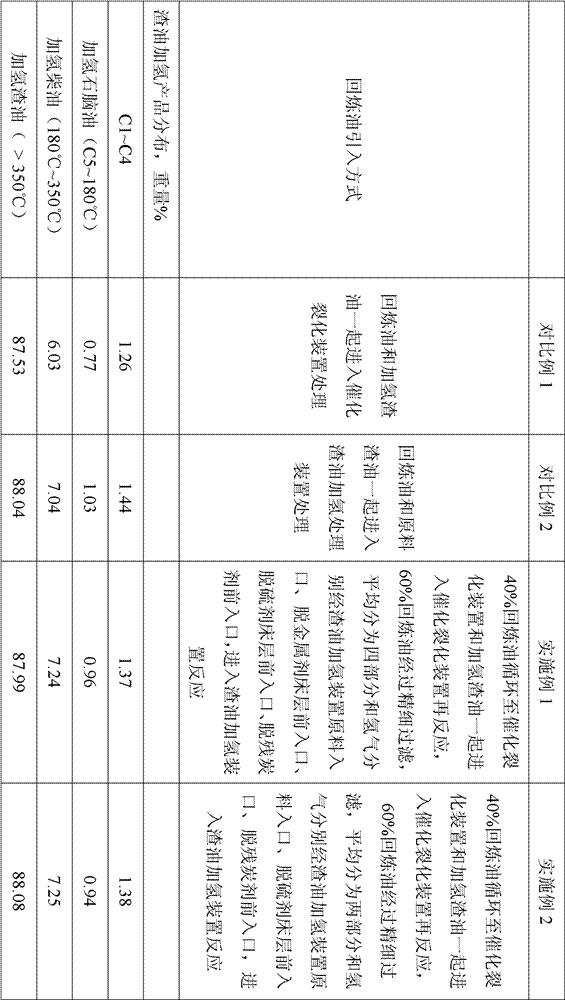
[0043] Kuwaiti residual oil and hydrogen enter the residual oil hydrogenation pilot plant together, after residual oil hydrogenation treatment, the reaction is carried out according to the conditions in Table 1, and the reaction products are separated into gas, hydrogenated naphtha, hydrogenated diesel oil, and hydrogenated residue oil; hydrogenated residual oil enters the catalytic cracking unit, and reacts according to the conditions in Table 1. The catalytic cracking products are divided into dry gas, liquefied gas, catalytic gasoline, catalytic diesel oil, catalytic cracking heavy cycle oil and oil slurry, and the refining oil adopts For heavy cycle oil, 40% of the recycled oil is recycled to the catalytic cracking unit and the hydrogenated residual oil enters the catalytic cracking unit for re-reaction. 60% of the recycled oil is finely filtered and divided into four parts on average and the hydrogen is respectively passed through the raw material inlet of the residual hydr...

Embodiment 2

[0045] Kuwaiti residual oil and hydrogen enter the residual oil hydrogenation pilot plant together, after residual oil hydrogenation treatment, the reaction is carried out according to the conditions in Table 1, and the reaction products are separated into gas, hydrogenated naphtha, hydrogenated diesel oil, and hydrogenated residue oil; the hydrogenated residual oil enters the catalytic cracking unit and reacts according to the conditions in Table 1. The catalytic cracking products are divided into dry gas, liquefied gas, catalytic gasoline, catalytic diesel, catalytic cracking heavy cycle oil and oil slurry. For circulating oil, 40% of the recycled oil is recycled to the catalytic cracking unit and the hydrogenated residual oil enters the catalytic cracking unit for re-reaction. 60% of the recycled oil is finely filtered and divided into two parts on average. The front inlet of the desulfurizer bed and the front inlet of the carbon removal catalyst bed enter the residual oil h...


PUM


Abstract

A residuum hydrotreatment-catalytic cracking combination technology of catalytic cracking recycle oil is characterized in that a material inlet is arranged in front of a metal removal agent bed layer, a desulfurizer bed layer, and a residual carbon removal agent bed layer of a device respectively, residuum and hydrogen enter the device to react through a device raw material port, hydrogenated residuum enters a catalytic cracking device and continuously reacts, one part of the recovery oil of the catalytic cracking device enters a hydrogenation device to react through one or more of four material inlets of a hydrotreatment device, and the residual recovery oil of the catalytic cracking device is cycled to the catalytic cracking device and enters the catalytic cracking device together with the hydrogenated residuum. The technology enables the operations of the residuum hydrotreatment-catalytic cracking combination technology to be flexible and efficient, and has the advantages of prolongation of the operation period of the residuum hydrotreatment device, improvement of the impurity removal rates of residuum hydrogenation products, reduction of the application amount of cold hydrogen, and increase of the yield of light oil having high added values.

Description

technical field [0001] The invention relates to a combined process of residual oil hydrotreating and catalytic cracking. Background technique [0002] At present, the world's oil refining and processing industry is facing the severe challenge of increasingly heavy and inferior crude oil resources. In 2008, my country's crude oil processing volume was 342 million tons, of which heavy crude oil processing volume reached 137 million tons, accounting for more than 40% of the total. As we all know, the proportion of residual oil in crude oil is usually 45-75%, and its properties are significantly inferior to fractions such as gas oil with a lower boiling range. Therefore, the pressure for deep processing of crude oil to maximize the production of light products and chemical raw materials naturally falls on on the residual oil. [0003] Among the optional technical routes for deep processing of residual oil, the combined process of residual oil hydrotreating-catalytic cracking i...

Claims


Application Information

Patent Timeline
IPC IPC(8): C10G69/00
Inventor 崔瑞利赵愉生赵元生谭青峰程涛于双林刘元东张志国那美琦周志远范建光张春光
Owner PETROCHINA CO LTD
Why Eureka
Try Eureka