Micro-fluidic chip and method for studying effect of fluid shearing force on cell with the micro-fluidic chip

A microfluidic chip, fluid shear force technology, applied in the field of biomedical research

Inactive Publication Date: 2012-12-12
DALIAN MEDICAL UNIVERSITY
View PDF4 Cites 9 Cited by
  • Summary
  • Abstract
  • Description
  • Claims
  • Application Information

AI Technical Summary

Problems solved by technology

The device for studying the effect of fluid shear force on cells in vitro is a loading device developed according to the principle of rheology. The basic principle is to use the flowing culture medium to generate shear force on the cells attached to the culture substrate. The parallel plate flow chamber is currently the A fluid shear force experimental loading device commonly used at home and abroad, but it is difficult to generate fluid shear force with multiple ratio changes in the same parallel plate flow chamber

Method used


Image

  • Micro-fluidic chip and method for studying effect of fluid shearing force on cell with the micro-fluidic chip
  • Micro-fluidic chip and method for studying effect of fluid shearing force on cell with the micro-fluidic chip
  • Micro-fluidic chip and method for studying effect of fluid shearing force on cell with the micro-fluidic chip

Examples


Embodiment 1

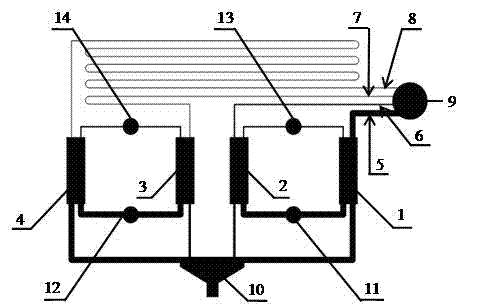
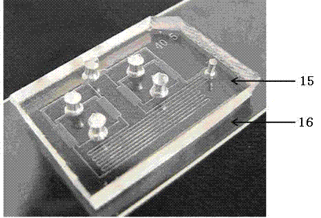
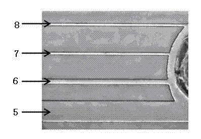
[0025] A microfluidic chip, the specific structure is as figure 1 As shown, its actual figure is shown in figure 2 As shown, the upper material of the chip is PDMS polymer, which is sealed to the lower glass surface by irreversible sealing technology, mainly composed of cell culture pool a 1, cell culture pool b 2, cell culture pool c 3, cell culture pool d 4 and The fluid channel a 5, the fluid channel b 6, the fluid channel c 7, the fluid channel d 8, the culture fluid sampling port 9 and the waste liquid pool 10; the fluid channel a 5, the fluid channel b 6, the fluid channel c 7 and The fluid channel d 8 starts from the culture solution inlet 9 together, and the ends of the above four fluid channels are respectively connected to the cell culture pool a 1, the cell culture pool b 2, the cell culture pool c 3, and the cell culture pool d 4 in sequence , and cell culture pool a 1, cell culture pool b 2, cell culture pool c 3 and cell culture pool d 4 are connected to the s...

Embodiment 2

[0027] Using the microfluidic chip in Example 1, connect the microsyringe pump to the culture solution inlet, perform perfusion of the culture solution at a flow rate of 0.08 μl / min, and measure the flow field distribution in the cell culture pool of the above-mentioned microfluidic chip , the flow fields in the four cell culture pools (1) cell culture pool a, (2) cell culture pool b, (3) cell culture pool c, and (4) cell culture pool d are evenly distributed, see Figure 4 .

Embodiment 3

[0029] Using the microfluidic chip in Example 1, connect the microsyringe pump to the culture solution inlet, and perfuse the culture solution at a flow rate of 0.08 μl / min, and measure the fluid shear in different cell culture pools of the above microfluidic chip The size of the force, in which (1) cell culture pool a, (2) cell culture pool b, (3) cell culture pool c, (4) cell culture pool d, the fluid shear force in cell culture pool a is far greater than The ratio of fluid shear force in cell culture pools b, c, and d is about 1:5:25:125, see Figure 5 .


PUM


Abstract

The invention provides a micro-fluidic chip and a method for studying an effect of fluid shearing force on a cell with the micro-fluidic chip. The micro-fluidic chip is composed of four cell culture inserts and four fluid passages, wherein the four cell culture inserts have the same size and are parallel mutually; a cell culture insert a and a cell culture insert b share one cell injection port and one cell waste reservoir; a cell culture insert c and a cell culture insert d share one cell injection port and one cell waste reservoir; the upper ends of the four cell culture inserts are separately connected with the four fluid passages; the lower ends of the four cell culture inserts are connected with the same waste reservoir; and the four fluid passages collectively start from a nutrient solution injection port, with the tail ends being connected with the four cell culture inserts respectively. The micro-fluidic chip can be used for studying the effect of the fluid shearing force on the cell.

Description

technical field [0001] The invention relates to the field of applying microfluidic chip technology to biomedical research, and particularly provides a microfluidic chip and a method for studying the effect of fluid shear force on cells. Background technique [0002] Fluid flow is a key regulatory factor for bone tissue to detect and respond to mechanical stimuli. Under the action of external force, fluid flows from high-strain areas to low-strain areas, and various types of cells in bone tissue are continuously exposed to the shear force caused by fluid flow. A series of reactions take place in the force. The device for studying the effect of fluid shear force on cells in vitro is a loading device developed according to the principle of rheology. The basic principle is to use the flowing culture medium to generate shear force on the cells attached to the culture substrate. The parallel plate flow chamber is currently the A fluid shear force experimental loading device commo...

Claims


Application Information

Patent Timeline
Patent Type & Authority Applications(China)
IPC IPC(8): C12M3/04C12Q1/02
CPCC12M23/16C12M23/34C12M23/40
Inventor 刘婷姣虞炜亮秦建华林炳承
Owner DALIAN MEDICAL UNIVERSITY
Why Eureka
Try Eureka