
Piezo-stack pump

A piezoelectric stack, pump body technology, applied in the direction of pumps, pumps with flexible working elements, liquid variable capacity machines, etc. The effect of easy processing, high output pressure and high bearing capacity

Inactive Publication Date: 2012-12-12
NANJING UNIV OF AERONAUTICS & ASTRONAUTICS
View PDF6 Cites 8 Cited by
  • Summary
  • Abstract
  • Description
  • Claims
  • Application Information

AI Technical Summary

Problems solved by technology

However, the output pressure of the piezoelectric plate or piezoelectric bimorph piezoelectric pump is small, and its carrying capacity is weak, so it cannot adapt to the higher requirements of the piezoelectric pump at the present stage.

Method used


Image

  • Piezo-stack pump
  • Piezo-stack pump
  • Piezo-stack pump

Examples


Embodiment Construction

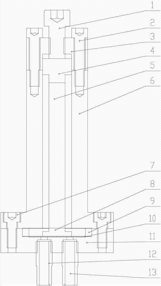
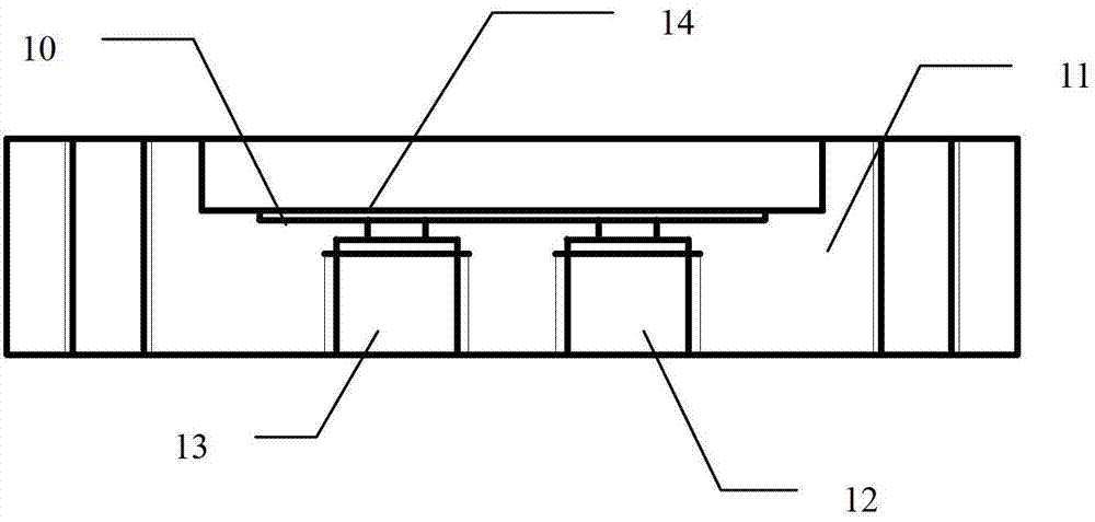
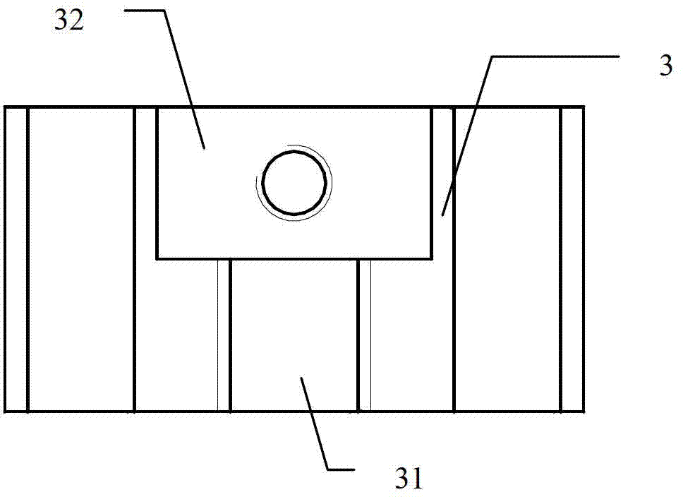
[0023] like figure 1 , figure 2 As shown, the piezoelectric stack pump of this embodiment includes a pump base 11 provided with a fluid inlet 13 and a fluid outlet 12, a pump body 6, a pump upper cover 3 and a piezoelectric stack 5 accommodated in the pump body 6, The fluid inlet 13 is provided with an inlet one-way valve 13, and the fluid outlet 12 is provided with an outlet one-way valve 12; the pump body 6 has a cylindrical cavity, and the piezoelectric stack 5 is accommodated in the cylindrical cavity. The electrical stack 5 is also cylindrical. A vibrating piston 8 is provided between one end of the piezoelectric stack 5 and the pump base 11, and a preloaded piston 4 is provided between the other end of the piezoelectric stack 5 and the pump upper cover 3; the vibrating piston 8 is pasted on the vibrating On the membrane 10 , a working fluid cavity 14 is formed between the vibration membrane 10 and the pump base 11 .

[0024] Specifically, the vibrating membrane 10 i...


PUM


Abstract

The invention discloses a piezo-stack pump, which comprises a pump base, a pump body, a top pump cap and a piezo-stack, the pump base is provided with a fluid inlet and a fluid outlet, the piezo-stack is contained in the pump body, a vibrating piston is arranged between one end of the piezo-stack and the pump base, and a pretightened piston is arranged between the other end of the piezo-stack and the top pump cap; the vibrating piston is stuck on a vibrating membrane, and a working fluid chamber is formed between the vibrating membrane and the pump base. All the parts in the piezo-stack pump are centralized in the pump body, so that space is saved, each part is convenient to assemble and easy to machine, the working fluid chamber is strictly closed, so that leakage is effectively prevented, and thereby the output power is increased. The piezo-stack pump can be widely applied in the fields of automobile engine fuel supply and robots.

Description

technical field [0001] The invention relates to a piezoelectric pump, in particular to a valved piezoelectric stack pump. [0002] Background technique [0003] The research on piezoelectric pumps began in the 1980s. It is a fluid pump designed and manufactured based on the principle of piezoelectric drive. The piezoelectric pump does not need an additional drive motor, but uses the inverse piezoelectric effect of the piezoelectric material to apply an alternating current signal to the piezoelectric stack to cause the piezoelectric stack to expand and contract, and then the volume of the pump chamber changes due to the expansion and contraction deformation. Cooperate with the import and export check valve to control the direction of the fluid, so as to realize the fluid delivery. Since traditional piezoelectric pumps are mostly in the form of piezoelectric bimorphs, the advantages of this type of piezoelectric pump are simple structure, small size, light weight, low energy...

Claims


Application Information

Patent Timeline
Patent Type & Authority Applications(China)
IPC IPC(8): F04B43/04
Inventor 裘进浩黄成志季宏丽
Owner NANJING UNIV OF AERONAUTICS & ASTRONAUTICS
Learn More