Bipolar junction transistor (BJT) auto-excitation type Zeta convertor with low main switch tube drive loss

A main switch tube and converter technology, which is applied in the output power conversion device, the conversion of DC power input to DC power output, instruments, etc. The effect of low loss and high light load efficiency

Active Publication Date: 2012-12-12
天津科迪特科技有限责任公司
View PDF4 Cites 6 Cited by
  • Summary
  • Abstract
  • Description
  • Claims
  • Application Information

AI Technical Summary

Problems solved by technology

The disadvantage of this circuit is that the driving unit of the main switching tube Q1 composed of driving resistor R1, PNP type BJT tube Q2, resistor R2, resistor R3 and capacitor C1 still has a large current flow when the main switching tube Q1 is turned off. Overdrive resistor R1, resulting in large drive loss of Q1, which affects the efficiency of the circuit, especially the light-load efficiency of the circuit

Method used


Image

  • Bipolar junction transistor (BJT) auto-excitation type Zeta convertor with low main switch tube drive loss
  • Bipolar junction transistor (BJT) auto-excitation type Zeta convertor with low main switch tube drive loss
  • Bipolar junction transistor (BJT) auto-excitation type Zeta convertor with low main switch tube drive loss

Examples


Embodiment 1

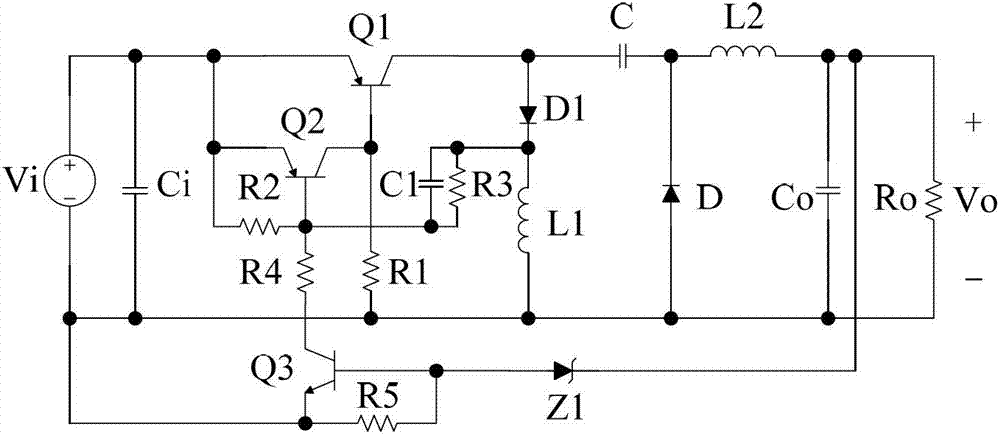
[0023] refer to figure 2 and Figure 6 , a BJT type self-excited Zeta converter with small driving loss of the main switching tube includes a Zeta converter composed of an input capacitor Ci, a PNP type BJT tube Q1, an inductor L1, a capacitor C, a diode D, a diode D1, an inductor L2 and a capacitor Co In the main circuit of the converter, the input capacitor Ci is connected in parallel with the DC voltage source Vi, the voltage across the output capacitor Co is the DC output voltage Vo, the load Ro is connected in parallel with the output capacitor Co, the positive terminal of the DC voltage source Vi is connected to the PNP type BJT tube Q1 The emitter is connected, the collector of the PNP type BJT tube Q1 is connected to one end of the inductor L1 and one end of the capacitor C, and the other end of the inductor L1 is connected to the negative end of the DC voltage source Vi, the negative end of the output voltage Vo, and the anode of the diode D , the other end of the c...

Embodiment 2

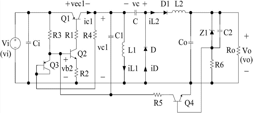
[0029] refer to image 3 and Figure 7 , this embodiment includes the main circuit of the Zeta converter composed of input capacitor Ci, PNP type BJT tube Q1, inductor L1, capacitor C, diode D, diode D1, inductor L2 and capacitor Co and resistor R1, resistor R2, resistor The driving unit of the main switching transistor Q1 composed of R3, resistor R4, capacitor C1, NPN type BJT transistor Q2 and PNP type BJT transistor Q3 also includes a current feedback branch. The current feedback branch includes NPN type BJT tube Q4, resistor R5, resistor R6, resistor R7, capacitor C2 and diode D2, the collector of NPN type BJT tube Q4 is connected to one end of resistor R5, and the other end of resistor R5 is connected to NPN The base of the type BJT tube Q2 is connected to the emitter of the PNP type BJT tube Q3, and the emitter of the NPN type BJT tube Q4 is connected to the negative terminal of the DC voltage source Vi, the anode of the diode D, one end of the capacitor Co and one end ...

Embodiment 3

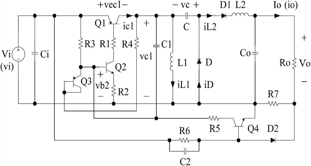
[0035] refer to Figure 4 and Figure 8 , this embodiment includes the main circuit of the Zeta converter composed of input capacitor Ci, PNP type BJT tube Q1, inductor L1, capacitor C, diode D, diode D1, inductor L2 and capacitor Co, and also includes the drive of the main switch tube Q1 unit. The driving unit of the main switching tube Q1 is composed of a resistor R1, a resistor R2, a resistor R3, a resistor R4, a capacitor C1, an NPN type BJT tube Q2 and a PNP type BJT tube Q3, and the collector of the NPN type BJT tube Q2 is connected to the resistor One end of R1 is connected, the other end of resistor R1 is connected to the base of PNP type BJT tube Q1, the emitter of NPN type BJT tube Q2 is connected to one end of resistor R2, and the other end of resistor R2 is connected to the negative end of DC voltage source Vi , the base of the NPN type BJT tube Q2 is connected to one end of the resistor R3 and the emitter of the PNP type BJT tube Q3, the other end of the resisto...


PUM


Abstract

A bipolar junction transistor (BJT) auto-excitation type Zeta convertor with a low main switch tube drive loss comprises a main loop of the Zeta convertor and a drive unit of a main switch tube Q1, wherein the main loop is assembled by an input capacitor Ci, a PNP type BJT Q1, an inductor L1, a capacitor C, a diode D, a diode D1, an inductor L2 and a capacitor Co, and the drive unit of the main switch tube Q1 is formed by a resistor R1, a resistor R2, a resistor R3, a resistor R4, a NPN type BJT Q2 and a PNP type BJT Q3. The converter has the advantages of being simple in circuit structure, few in component, low in main switch tube drive loss and high in circuit efficiency during light load.

Description

technical field [0001] The invention relates to a self-excited direct current-direct current (DC-DC) converter, which is applied to a switching stabilized voltage or current-stabilized power supply, a high-brightness LED drive circuit, etc., in particular to a self-excited Zeta converter. Background technique [0002] Compared with linear (stabilized voltage or steady current) regulators and other excited DC-DC converters, self-excited DC-DC converters have significant advantages of high cost performance. figure 1 Given is a BJT (bipolar transistor) type self-excited Zeta converter with simple circuit structure and few components, including input capacitor Ci, PNP type BJT tube Q1, diode D1, inductor L1, capacitor C , diode D, inductor L2 and the main circuit of the Zeta converter composed of output capacitor Co, the input capacitor Ci is connected in parallel with the DC voltage source Vi, the voltage across the output capacitor Co is the DC output voltage Vo, the load Ro i...

Claims


Application Information

Patent Timeline
Patent Type & Authority Applications(China)
IPC IPC(8): H02M3/155H05B37/02
Inventor 陈怡王正仕陈晋音南余荣
Owner 天津科迪特科技有限责任公司
Why Eureka
Try Eureka