Permanent magnet, method for producing same, and motor and power generator each using same
A technology of permanent magnets and elements, applied in the fields of variable magnetic flux motors and variable magnetic flux generators, can solve problems such as rising steepness, and achieve the effect of suppressing rising
- Summary
- Abstract
- Description
- Claims
- Application Information
AI Technical Summary
Problems solved by technology
Method used
Image
Examples
Embodiment 1
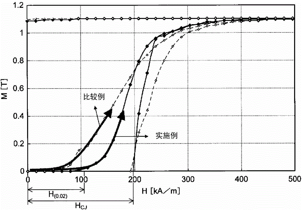
[0079] Weigh each raw material so that its composition is (Sm 0.85 Nd 0.15 )(Fe 0.28 Zr 0.025 Cu 0.05 co 0.47 ) 7.8 , and then arc melting in an Ar atmosphere to produce alloy ingots. The alloy ingot was heat-treated under the condition of 1170° C.×1 hour in an Ar atmosphere, coarsely pulverized, and finely pulverized by a jet mill to prepare an alloy powder. The alloy powder was pressurized in a magnetic field to form a pressed powder, and then sintered at 1190° C. for 3 hours in an Ar atmosphere, followed by heat treatment at 1170° C. for 3 hours to produce a sintered body. This heat treatment is performed for solution treatment.
[0080] Next, the sintered body after the solution treatment was heat-treated under the condition of 730° C.×1.5 hours as the first aging treatment, and then slowly cooled to room temperature at a cooling rate of 2° C. / min. Next, the sintered body after the first aging treatment was heat-treated as the second aging treatment under the condi...
Embodiment 2~4
[0082] Sintered magnets were produced in the same manner as in Example 1, except that alloy powders having the compositions shown in Table 1 were used. The first and second aging treatment conditions are the same as in Example 1. Here, the temperatures TB (° C.), [TB-50 (° C.)], and [TB+50 (° C.)] based on the respective alloy compositions are shown in Table 2. The sintered magnet thus obtained was used for the characteristic evaluation described later.
Embodiment 5
[0086] Weigh each raw material so that its composition is (Sm 0.9 Nd 0.1 )(Fe 0.34 Zr 0.03 Cu 0.05 co 0.58 ) 7.5 , and then arc melting in an Ar atmosphere to produce alloy ingots. The alloy ingot was placed in a quartz nozzle and melted by high-frequency induction heating. The molten body was then poured into a cooling roll rotating at a peripheral speed of 0.6 m / sec and continuously solidified to produce a thin ribbon. After the ribbon was roughly pulverized, it was finely pulverized by a jet mill to prepare alloy powder. This alloy powder was pressurized in a magnetic field to form a pressed powder, and then sintered at 1200° C. for 1 hour in an Ar atmosphere, followed by heat treatment at 1180° C. for 4 hours to produce a sintered body.
[0087] Next, the sintered body after the solution treatment was heat-treated for 1.5 hours at 850°C as the first aging treatment, and then heat-treated at 875°C for 4 hours as the second aging treatment, and then heat-treated at 1....
PUM
| Property | Measurement | Unit |
|---|---|---|
| thickness | aaaaa | aaaaa |
| particle size | aaaaa | aaaaa |
| thickness | aaaaa | aaaaa |
Abstract
Description
Claims
Application Information
 - R&D
- Intellectual Property
- Life Sciences
- Materials
- Tech Scout
- Unparalleled Data Quality
- Higher Quality Content
- 60% Fewer Hallucinations
Browse by: Latest US Patents, China's latest patents, Technical Efficacy Thesaurus, Application Domain, Technology Topic, Popular Technical Reports.
© 2025 PatSnap. All rights reserved.Legal|Privacy policy|Modern Slavery Act Transparency Statement|Sitemap|About US| Contact US: help@patsnap.com


