
Efficient cutting device of ball-end milling cutter

A technology of ball end milling cutter and transmission device, which is applied to milling machine equipment, details of milling machine equipment, metal processing equipment, etc., and can solve problems such as easy wear and chipping of the center of the tool

Inactive Publication Date: 2012-12-19
邵枫
View PDF4 Cites 1 Cited by
  • Summary
  • Abstract
  • Description
  • Claims
  • Application Information

AI Technical Summary

Problems solved by technology

Due to the above reasons, the center of the tool is easy to chip, and the part close to the center is easy to wear

Method used


Image

  • Efficient cutting device of ball-end milling cutter
  • Efficient cutting device of ball-end milling cutter
  • Efficient cutting device of ball-end milling cutter

Examples


Embodiment 1

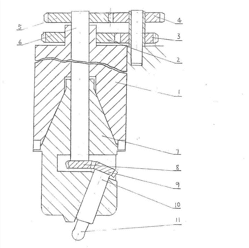
[0014] Such as figure 1 As shown, the main shaft 1 rotates to drive the gear 2, the gear 2 drives the double gears 3, 4, the gear 4 drives the intermediate shaft 6 through the gear 5, the intermediate shaft 6 drives the driven shaft 10 through a pair of bevel gears 8, 9, and the driven shaft 10 Make the cutter 11 rotate. The connecting body 7 (the connecting body is not required for a special device) makes the driven shaft rotate around the main shaft while rotating on its own.

Embodiment 2

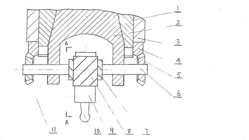
[0016] Such as figure 2 As shown, the main shaft 1 drives the connecting body 2, and the connecting body 2 makes the transverse shaft 6 rotate, and drives the bevel gear 5 to rotate around the center of the main shaft, and the bevel gear ring gear 4 meshing with it is installed on the sleeve 3 (or on the fuselage) , is non-rotating, so the bevel gear 5 rotates at the same time, and the transverse shaft 6 rotates through a pair of 45 helical gears 7, 8 to drive the driven shaft 9, and the driven shaft 9 makes the cutter 10 rotate. Bevel gear 11 only plays a balancing role. The characteristic of this structure is that the angle of the driven shaft can be adjusted.

Embodiment 3

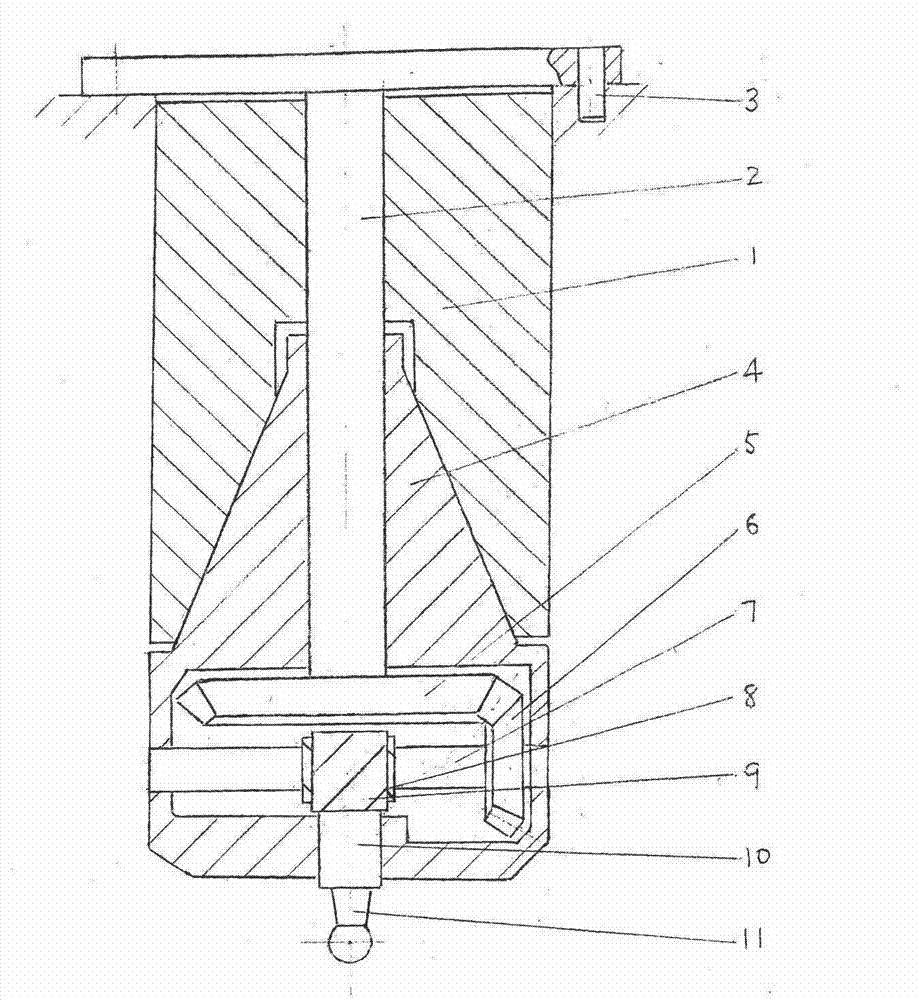
[0018] Such as image 3 As shown, the intermediate shaft 2 is fixed on the upper end of the end milling head by the pin 3 and does not rotate; the bevel gear 5 is installed on the intermediate shaft and does not rotate. When the main shaft 1 rotates, the connecting body 4 rotates together, and the bevel gear 6 meshing with the bevel gear ring gear 5 rotates around the center and rotates on its own. The bevel gear 6 drives the horizontal axis to rotate, and the horizontal axis makes the driven shaft and the center rotate at an included angle through a pair of helical gears, and rotate by itself; the included angle can be adjusted. The driven shaft rotates the tool.


PUM


Abstract

A mechanical transmission device is capable of enhancing the cutting property of a ball-end milling cutter, and comprises a driving shaft, an intermediate shaft, a plurality of gears (cylindrical gear, internal gear, bevel gear, spiral gear), a driven shaft and a milling cutter; the driving shaft and the driven shaft form an included angle; when a main shaft is driven to rotate by a power source, the main shaft drives the driven shaft to rotate around the main shaft by the gears and rotates around the axis. The centre of the ball-end is corrected by a scale or by other methods, so as to be arranged on the centre line of the main shaft. The method is simple and convenient. Therefore, the centre part of the ball-end milling cutter does not participate in cutting due to the fact that the centre part is likely to tip and wear. The part of the end face of the ball-end milling cutter which does not participate in cutting is increased along with the increment of included angle between the driving shaft and the driven shaft. The centre of the ball-end milling cutter is avoided from tipping, thereby enhancing the wearing resistance of the cutter, fastening the cutter feeding speed, and improving the cutting efficiency.

Description

technical field [0001] The invention relates to a device in the technical field of mechanical transmission and metal cutting, in particular to a spherical milling device. Background technique [0002] Find through prior art retrieval, " milling worker " (comprising previously published " milling worker ") all useful boring tool or the method for milling cutter processing concave spherical surface of latest publication. Due to the difficulty of tool setting, the machining accuracy is low; the most important thing is that the tool rotates, and the workpiece must also rotate. It is only used to process concave spherical surfaces, and its application range is very narrow. [0003] As profiling milling machines, especially CNC milling machines, are becoming more and more common, ball end milling cutters can be used more and more widely for free-form surfaces. The disadvantages of the ball end milling cutter are obvious. Some articles analyze its cutting force, saying that the c...

Claims


Application Information

Patent Timeline
IPC IPC(8): B23C3/02
Inventor 邵吕林
Owner 邵枫
Learn More