Wear-resisting weak-abrasiveness bionic tool joint

A drill pipe joint and abrasive technology, applied in the field of bionic coupling, can solve the problems of increased wear of the upper part of the drill pipe joint and the inner wall of the casing, the life cannot meet the drilling speed increase, and increase the loss of mud along the way, so as to reduce the occurrence of downhole accidents Probability, prolonging the life of drill pipe, improving the effect of drilling quality

Inactive Publication Date: 2012-12-19
JILIN UNIV
View PDF9 Cites 3 Cited by
  • Summary
  • Abstract
  • Description
  • Claims
  • Application Information

AI Technical Summary

Problems solved by technology

However, there is a large difference in material properties between the wear-resistant layer and the drill pipe joint body, and the bonding force between the two is poor after welding. It is greatly affected by environmental and human factors, and cracks are easy to form
During drilling, the wear-resistant band material is prone to local shedding, resulting in increased wear on the upper part of the drill pipe joint and the inner wall of the casing
From the perspective of energy saving, since the wear-resistant belt is higher than the outer diameter of the joint by a certain size, the loss along the mud will be increased, and the pressure loss will increase.
From the perspective of casing protection, because tungsten carbide wears heavily on the casing wall, the content of tungsten carbide (wear-resistant material) in the wear-resistant band is required to be within a certain range, and its life is far from meeting the requirements of drilling speed increase. need

Method used


Image

  • Wear-resisting weak-abrasiveness bionic tool joint
  • Wear-resisting weak-abrasiveness bionic tool joint
  • Wear-resisting weak-abrasiveness bionic tool joint

Examples


Embodiment Construction

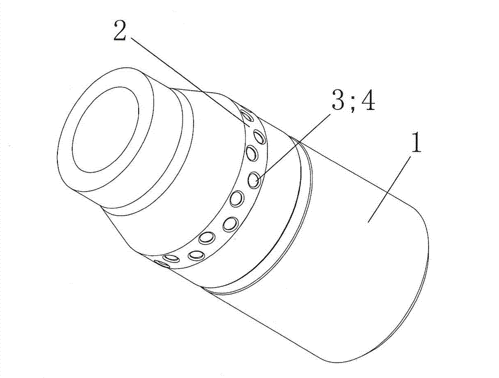
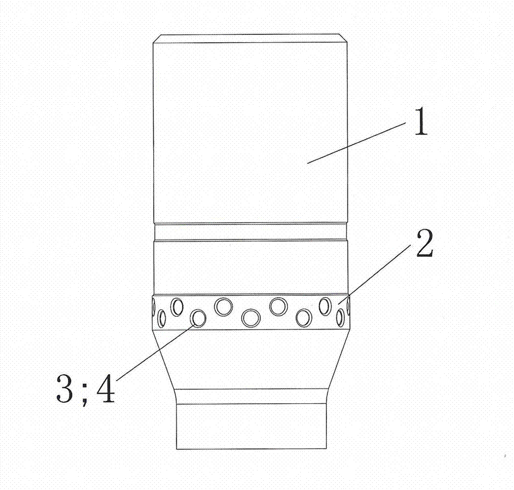
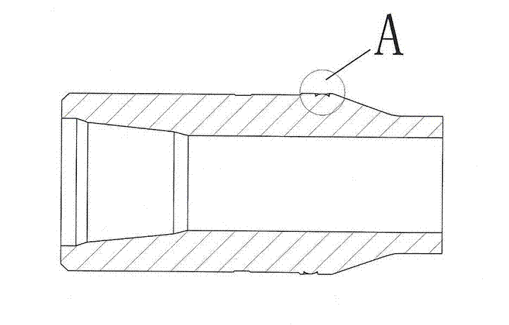
[0015] see figure 1 , figure 2 , image 3 and Figure 4 As shown, in this embodiment, several regularly arranged concave non-smooth structural units 3 are arranged on the bionic wear-resistant belt 2 of the drill pipe joint 1, and each concave non-smooth structural unit 3 is provided with a convex hull type non-smooth structural unit 3. The structural unit 5, the depth of the concave non-smooth structural unit 3 is equal to the entire height of the convex hull non-smooth structural unit 5, the aperture of the concave non-smooth structural unit 3 is 0.001~0.1 mm smaller than the diameter of the convex hull non-smooth structural unit 5, and the concave The top of the pit non-smooth structure unit 3 is a concave pit edge surface arc transition 4, which is combined with the low friction coefficient and high wear-resistant convex hull non-smooth structure unit 5 through interference fit to form a wear-resistant non-smooth structure surface. The top surface of the combined conve...


PUM


Abstract

The invention discloses a wear-resisting weak-abrasiveness bionic tool joint, which is characterized in that a plurality of pit unsmooth structure units which are regularly distributed are arranged on a bionic wear-resisting belt of the tool joint, each pit unsmooth structure unit is internally provided with a convex-hull-shaped unsmooth structure unit, the depth of the pit unsmooth structure unit is identical to the overall height of the convex-hull unsmooth structure unit, the aperture of each pit unsmooth structure unit is 0.001 to 0.1mm smaller than the diameter of the convex-hull unsmooth structure unit, the top of each pit unsmooth structure unit is in arc transition of a pit prismatic surface to be connected together with the low-friction-coefficient high-wear-resisting convex-hull unsmooth structure unit in an interference fit way to form a wear-resisting unsmooth structure surface, and the top surface of the combined convex-hull unsmooth structure unit is leveled to the surface of the tool joint. The wear-resisting weak-abrasiveness bionic tool joint has characteristics that the service life of a drill pipe is prolonged, the abrasion on a bushing is reduced, the anti-viscosity is strong, the wear resistance of the drill pipe is improved, and the like, and can effectively reduce the underground accident, improve the drilling quality and save the drilling cost.

Description

technical field [0001] The invention belongs to the technical field of bionic coupling, and relates to exploration and drilling for petroleum and coal, especially to bionic non-smooth surface and material, non-smooth form and structure ternary coupling element, especially to a wear-resistant and weak abrasive coupling Bionic drill pipe joints are widely used in various drill pipes. Background technique [0002] At present, it is generally used at home and abroad to weld a layer of special wear-resistant tape on a certain position of the drill pipe joint to improve wear resistance and reduce wear on the casing. However, the material properties between the wear-resistant layer and the drill pipe joint body are greatly different, and the bonding force between the two is poor after welding, which is greatly affected by environmental and human factors, and cracks are easy to form. During drilling, the wear-resistant band material is prone to local shedding, resulting in increase...

Claims


Application Information

Patent Timeline
Patent Type & Authority Applications(China)
IPC IPC(8): E21B17/02
Inventor 孙友宏高科马宇刘宝昌徐小健
Owner JILIN UNIV
Why Eureka
Try Eureka