Thermal power plant and united thermodynamic system for thermal power plant

A thermal system and thermal power plant technology, applied in the field of electric power equipment, can solve the problems of small power generation capacity, loss of working capacity, and waste of back pressure units, so as to improve thermal cycle efficiency, improve operational flexibility, and reduce pollutant emissions Effect

Active Publication Date: 2012-12-19
CHINA POWER ENG CONSULTING GRP CORP EAST CHINA ELECTRIC POWER DESIGN INST +1
View PDF5 Cites 19 Cited by
  • Summary
  • Abstract
  • Description
  • Claims
  • Application Information

AI Technical Summary

Problems solved by technology

[0003] For the double-reheat condensing unit that uses steam extraction in the middle of the steam turbine to supply heat to the outside, there are two main problems: first, the steam volume of the steam extraction in the middle of the steam turbine accounts for a small proportion of the total steam volume of the steam turbine, and the heat supply is small; , the pressure of the steam supply is required to be stable, but the pressure of the steam extraction in the middle of the turbine decreases with the decrease of the load of the steam turbine. functional loss
Moreover, for high-pressure heating of about 5MPa, in order to meet the low-load pressure requirements, it is necessary to throttle from the main steam (high-load about 25MPa); (High load about 6MPa) throttling, so there is a large throttling loss
[0005] For the back-pressure unit that uses the steam turbine exhaust steam of the back-pressure unit to supply heat to the outside, the main problems are: first, the power generation of the unit changes with the heat supply, and the power generation decreases when the heat supply decreases. The generator set shuts down during heating; secondly, the power generation capacity of the back pressure unit is small, the largest back pressure unit in China is about 80MW, which is far lower than the conventional double reheat condensing steam generator set (300~1000MW)
Therefore, the investment is large, and there is a certain degree of waste at the same time

Method used


Image

  • Thermal power plant and united thermodynamic system for thermal power plant
  • Thermal power plant and united thermodynamic system for thermal power plant
  • Thermal power plant and united thermodynamic system for thermal power plant

Examples


Embodiment Construction

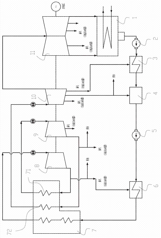
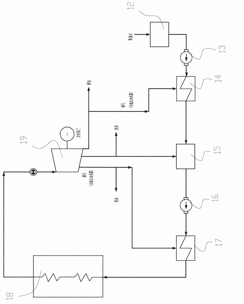
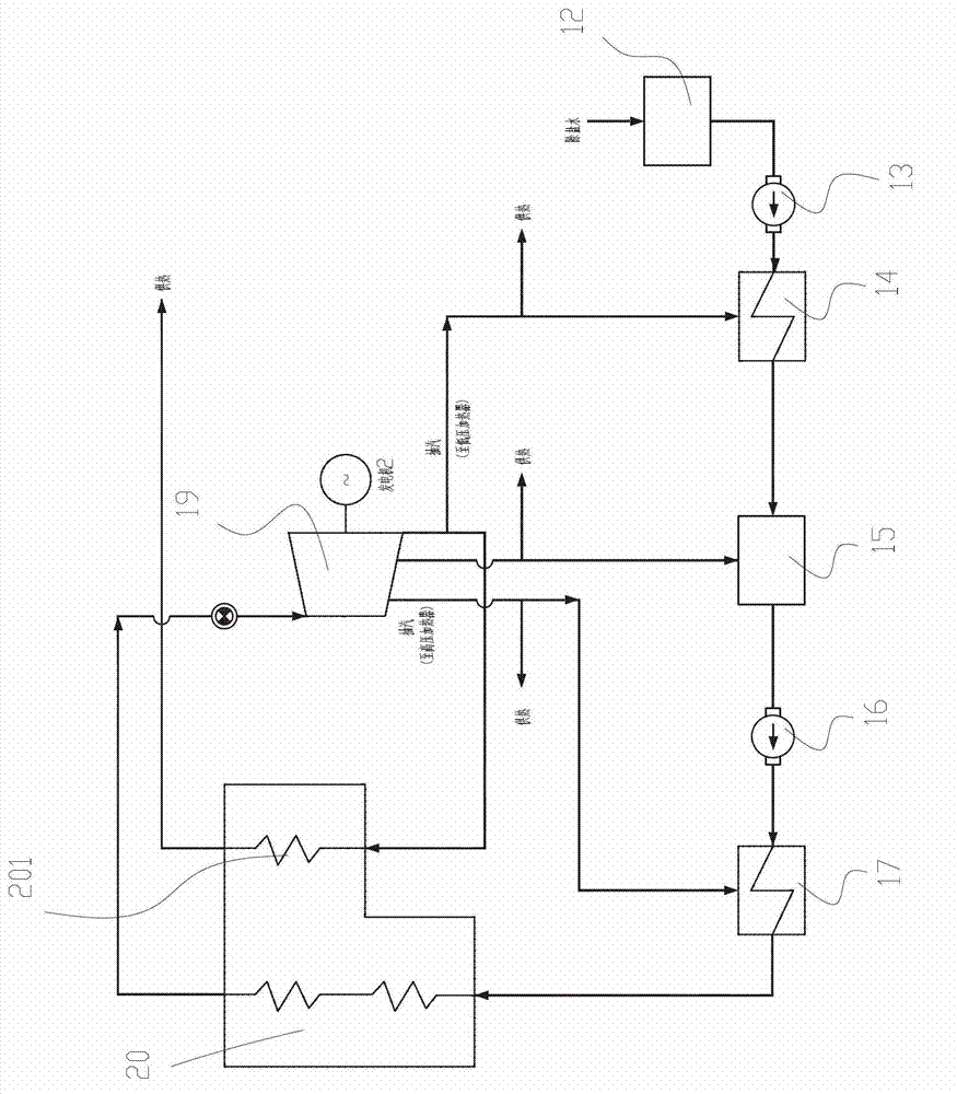
[0030] Preferred embodiments of the present invention will be described in detail below with reference to the accompanying drawings, so as to better understand the purpose, features and advantages of the present invention. It should be understood that the embodiments shown in the drawings are not intended to limit the scope of the present invention, but only to illustrate the essence of the technical solutions of the present invention. In the present invention, the same or similar components in each embodiment are given the same reference numerals.

[0031] Hereinafter, main technical terms of the present invention will be described.

[0032] In this paper, heat recovery refers to recovering the latent heat of vaporization of steam to improve the efficiency of thermal cycle.

[0033] In this paper, double reheating refers to the fact that steam enters the boiler twice during the work of the steam turbine, and returns to the steam turbine to continue to work after heating.

...


PUM


Abstract

The invention discloses a thermal power plant and a united thermodynamic system for the thermal power plant. The thermal power plant comprises a secondary reheating coagulated steam unit and a backpressure unit; the united thermodynamic system comprises a thermodynamic system of the secondary reheating coagulated steam unit and the thermodynamic system of the backpressure unit; a reheating system from a condenser to a deaerator is shared by the thermodynamic system of the secondary reheating coagulated steam unit and the thermodynamic system of the backpressure unit; the condensed water of the secondary reheating coagulated steam unit and the replenished desalted water of the backpressure unit pass through the shared reheating system and then are divided into two paths; one path enters the secondary reheating coagulated steam unit; and the other path enters the backpressure unit. The united thermodynamic system provided by the invention can meet the industrial requirements of large capacity and high parameter heat supply; the thermodynamic cycle efficiency is greatly increased; the fuel consumption is reduced; the pollutant emission is reduced; and meanwhile, the investment of the thermal power plant is greatly reduced.

Description

technical field [0001] The invention relates to power equipment, in particular to a thermal system in a thermal power plant. Background technique [0002] In the prior art, in power plants that use steam turbines for power generation and heat supply, the middle extraction steam of the steam turbine of the double reheat condensing unit is usually used for external heat supply, or the exhaust steam of the steam turbine of the back pressure unit is used for external heat supply. [0003] For the double-reheat condensing unit that uses steam extraction in the middle of the steam turbine to supply heat to the outside, there are two main problems: first, the steam volume of the steam extraction in the middle of the steam turbine accounts for a small proportion of the total steam volume of the steam turbine, and the heat supply is small; , the pressure of the steam supply is required to be stable, but the pressure of the steam extraction in the middle of the turbine decreases with ...

Claims


Application Information

Patent Timeline
Patent Type & Authority Applications(China)
IPC IPC(8): F01K17/02F01K11/02
CPCY02E20/14
Inventor 陈仁杰曹沂叶勇健沈维君施刚夜贺益中申松林张剑林磊邓文祥
Owner CHINA POWER ENG CONSULTING GRP CORP EAST CHINA ELECTRIC POWER DESIGN INST
Why Eureka
Try Eureka