Linear stabilizer with low pressure difference

A low-dropout linear, voltage-stabilizer technology, applied in instruments, regulating electrical variables, control/regulating systems, etc., can solve the problem of increasing static power consumption and low-frequency noise of circuits, increasing circuit-level design scale, increasing circuit complexity and Cost and other issues, to achieve the effect of low overall power consumption, saving layout area, and improving overshoot and undershoot

Inactive Publication Date: 2012-12-19
墨威嘉慧(杭州)科技有限公司
View PDF5 Cites 25 Cited by
  • Summary
  • Abstract
  • Description
  • Claims
  • Application Information

AI Technical Summary

Problems solved by technology

However, the added two comparator loops increase the static power consumption and low-frequency noise in the circuit while significantly increasing the circuit-level design scale.
M...

Method used


Image

  • Linear stabilizer with low pressure difference
  • Linear stabilizer with low pressure difference
  • Linear stabilizer with low pressure difference

Examples


Embodiment 1

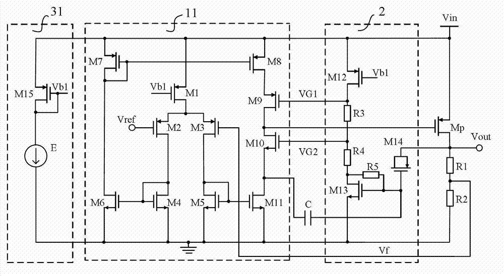
[0030] Such as image 3 As shown, a low-dropout linear regulator includes: a bias voltage generation circuit 31, an error amplifier 11, an output transistor Mp, a compensation capacitor C and a fast response circuit 2; the output transistor Mp is a PMOS transistor, and its source is connected to the input Voltage Vin; where:

[0031] The bias voltage generation circuit 31 is used to provide the bias voltage Vb1 to the error amplifier 11 and the fast response circuit 2; in this embodiment, the bias voltage generation circuit 31 is composed of a PMOS transistor M15 and a current source E; wherein, the PMOS transistor M15 The source is connected to the input voltage Vin, the gate and drain of the PMOS transistor M15 are connected to one end of the current source E to generate a bias voltage Vb1, and the other end of the current source E is grounded.

[0032] The fast response circuit 2 is used to sense the load transient step by collecting the output voltage Vout of the output t...

Embodiment 2

[0040] Such as Figure 4 As shown, a low-dropout linear regulator includes: a bias voltage generating circuit 32, an error amplifier 12, an output transistor Mp, a compensation capacitor C and a fast response circuit 2; the output transistor Mp is a PMOS transistor, and its source is connected to the input Voltage Vin; where:

[0041] The bias voltage generating circuit 32 is used to provide bias voltages Vb1 and Vb2 to the fast response circuit 2 and the error amplifier 12 respectively; in this embodiment, the bias voltage generating circuit 32 is composed of a PMOS transistor M15, an NMOS transistor M16 and a current source E ; wherein, the source of the PMOS transistor M15 is connected to the input voltage Vin, the gate and drain of the PMOS transistor M15 are connected to one end of the current source E to generate a bias voltage Vb1, and the other end of the current source E is connected to the drain of the NMOS transistor M16 It is connected to the gate and generates a ...


PUM


Abstract

The invention discloses a linear stabilizer with a low pressure difference, which comprises a bias voltage generating circuit, an error amplifier, an output pipe and a quick response circuit, wherein the quick response circuit is used for sensing a load transient phase step by collecting an output voltage of the output pipe and supplying a pair of control signals to the error amplifier after the output voltage is coupled, reversely amplified and subjected to level shifting; the error amplifier is used for collecting a feedback voltage of the output pipe through a voltage-dividing network, comparing the feedback voltage with a reference voltage and performing direct current voltage stabilization on the output voltage of the output pipe; and the error amplifier has a structure of a transient switch pipe and is used for transiently switching an output-level current of the error amplifier according to the control signals so as to generate a driving signal to control the output pipe to response to the load transient phase step. Thus, the linear stabilizer provided by the invention meets the industrial design demand on the high-performance voltage-stabilized source, and the overshoot and undershoot of the output voltage under the condition of the load transient phase step are obviously improved.

Description

technical field [0001] The invention belongs to the technical field of integrated circuits, and in particular relates to a low-dropout linear regulator. Background technique [0002] Low-dropout linear regulator LDO (low-dropout regulator) is widely used in various analog, mixed-signal and radio frequency integrated circuit systems, such as implanted medical electronic equipment, mobile communication equipment, or power supplies for consumer electronics management module. It is used to provide a stable output voltage with load capability, and has the advantages of low static power consumption, low noise, and small circuit scale. Early low-dropout linear regulators usually need to add an external capacitor above the uF level to the output to ensure a good output load step response. However, more and more of the above-mentioned electronic devices adopt fully integrated system-on-chip (system-on-chip) to reduce size and save cost, and low dropout linear regulators without ext...

Claims


Application Information

Patent Timeline
IPC IPC(8): G05F1/56
Inventor 邹磊
Owner 墨威嘉慧(杭州)科技有限公司
Why Eureka
Try Eureka