Grooving blade

A blade and grooving technology, applied in milling cutters, milling machine equipment details, manufacturing tools, etc., can solve the problems of time-consuming and labor-intensive, and the machining accuracy cannot be guaranteed, and achieve the effects of less loss, improved production efficiency, and high machining accuracy.

Inactive Publication Date: 2012-12-26
WUXI YUTIAN PRECISION TOOL
View PDF0 Cites 5 Cited by
  • Summary
  • Abstract
  • Description
  • Claims
  • Application Information

AI Technical Summary

Problems solved by technology

When the cutting edge is worn, the tool must be replaced, and the tool needs to be re-set, which is time-consuming and laborious. After re-setting, the machining accuracy cannot be guaranteed.

Method used


Image

  • Grooving blade
  • Grooving blade
  • Grooving blade

Examples


Embodiment Construction

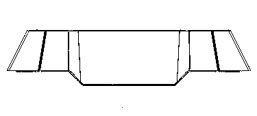
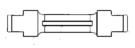
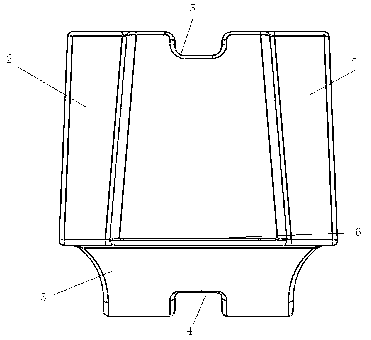
[0011] Such as figure 1 , 2 , 3, 4 shown

[0012] The grooving blade of this embodiment has an integrally formed structure. The blade main body 1 is a four-sided platform with an isosceles trapezoidal side. The front and rear sides of the blade main body are respectively provided with a "concave"-shaped boss 2. The boss cooperates with the groove on the milling cutter disc base to limit the longitudinal displacement of the blade. The bottom surface of the blade body is provided with a trapezoidal boss 3, and the bottom surface of the trapezoidal boss is provided with a bottom positioning groove. 4. A top positioning groove 5 is provided on the top surface of the blade main body. The above two positioning grooves 4, 5 cooperate with the positioning keys arranged on the milling cutter disc to limit the lateral displacement of the blade. The cutting edge of the blade 6 It is arranged on the bottom edge of the trapezoidal sides on the left and right sides of the blade main body....


PUM


Abstract

The invention relates to a grooving blade, characterized in that: the grooving blade is manufactured by integral molding, the blade body (1) is a quadrangular prism that has a side surface which is an isosceles trapezoid, the front and back surfaces of the blade body are respectively provided with a concave-shaped boss (2), the bottom of the blade body is provided with a boss (3) that has a side surface which is a trapezoid, the bottom of the trapezoid boss is provided with a bottom locating slot (4), the top surface of the blade body is provided with a top locating slot (5), and the cutting edge (6) of the blade is arranged at the bottom edges of the side surfaces of the two side trapezoid of the blade body. When the grooving blade works, the grooving blade is fixed on a facing cutter, the locating slot fits a locating key arranged on the base of the facing cutter to locate the cutter; when one side of the cutting edge is worn down, just the turning of the blade is needed, and the other side of the cutting edge is used. According to the invention, the cutting blade has a centrally symmetric structure, continuous work can be conducted without need for presetting the cutter again after turning, and the processing precision is high.

Description

technical field [0001] The invention relates to a cutting tool, in particular to a cutting blade for grooving. Background technique [0002] The grooving tools in the prior art generally have a thin blade structure, and when the workload of grooving is heavy, the blade is easy to wear. When the cutting edge is worn out, the tool must be replaced, and the tool needs to be re-set, which is time-consuming and laborious. After the re-set, the machining accuracy cannot be guaranteed. Contents of the invention [0003] In order to overcome the above-mentioned technical defects, the object of the present invention is to provide a grooving insert which is not easy to wear and has multiple cutting edges. [0004] In order to solve the above technical problems, the technical solution adopted in the present invention is: [0005] A grooving blade, characterized in that it has an integrated structure, the blade body (1) is a four-sided platform with an isosceles trapezoidal side, an...

Claims


Application Information

Patent Timeline
Patent Type & Authority Applications(China)
IPC IPC(8): B23C5/02B23C5/20B23C3/28
Inventor 朱胜雷
Owner WUXI YUTIAN PRECISION TOOL
Why Eureka
Try Eureka