Filament drawing and winding device

A technology of winding device and drafting device, which is applied in the direction of stretch spinning, clustering of newly extruded filaments, textiles and papermaking, etc., which can solve the problems affecting the increase of filament production, potential safety hazards, and excessive equipment. Achieve the effects of improving quality and quality, reducing manufacturing costs, and extending spinning time

Active Publication Date: 2012-12-26
BEIJING CHONGLEE MACHINERY ENG
View PDF11 Cites 3 Cited by
  • Summary
  • Abstract
  • Description
  • Claims
  • Application Information

AI Technical Summary

Problems solved by technology

It can be seen that the second defect of the traditional filament drawing and winding device is: the equipment is too high, which greatly increases the manufacturing cost of the equipment, the installation cost of the equipment, the infrastructure cost of the factory building and the labor cost of spinning. There are certain safety hazards, and the spinning time is long, which affects the increase of filament production and produces a large amount of spinning waste
Also, because the columns of the operating steel platform and the winding head are arranged at intervals, in order to facilitate the installation of the raw head and the winding head, push in and pull out for maintenance, there is a restrictive relationship between the arrangement of the operating steel platform, the column and the winding head, so in When determining the pitch of the spinning position, it is necessary to reserve space for the operation of the equipment, and the pitch of the spinning position cannot be further reduced. It can be seen that the third defect of the traditional filament drafting and winding device is : The equipment occupies a large area, the arrangement of the spinning positions is not flexible, and the area of ​​the plant is not fully utilized, which further affects the increase in the production of filaments
In addition, since the winding head in the winding device is separated from the machine frame, the traditional filament drawing and winding device has high requirements on the horizontality of the ground rail during installation and commissioning

Method used


Image

  • Filament drawing and winding device
  • Filament drawing and winding device
  • Filament drawing and winding device

Examples


Embodiment Construction

[0040] The present invention will be further described in detail below in conjunction with the accompanying drawings and specific embodiments.

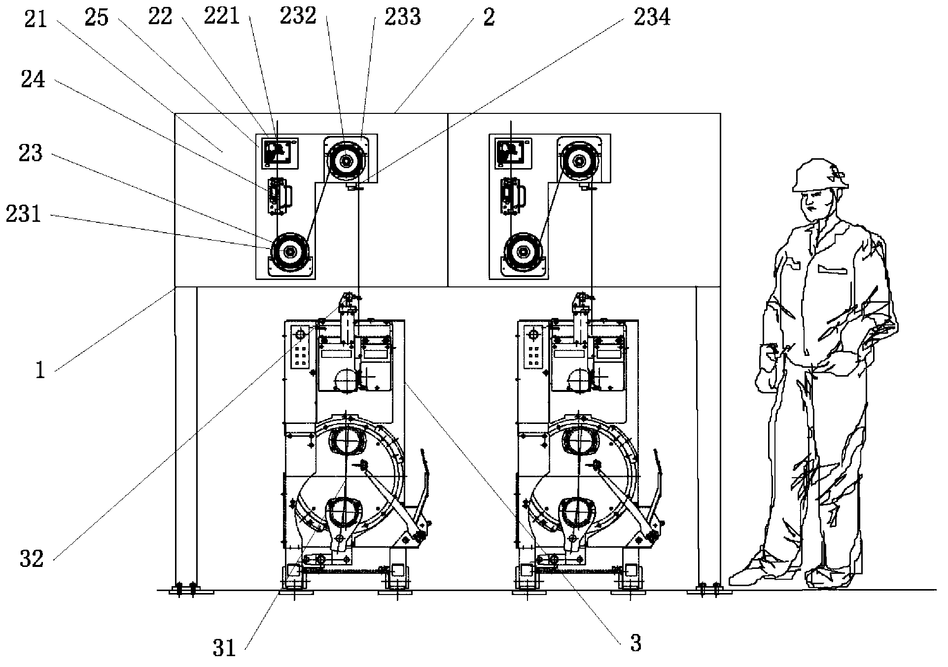
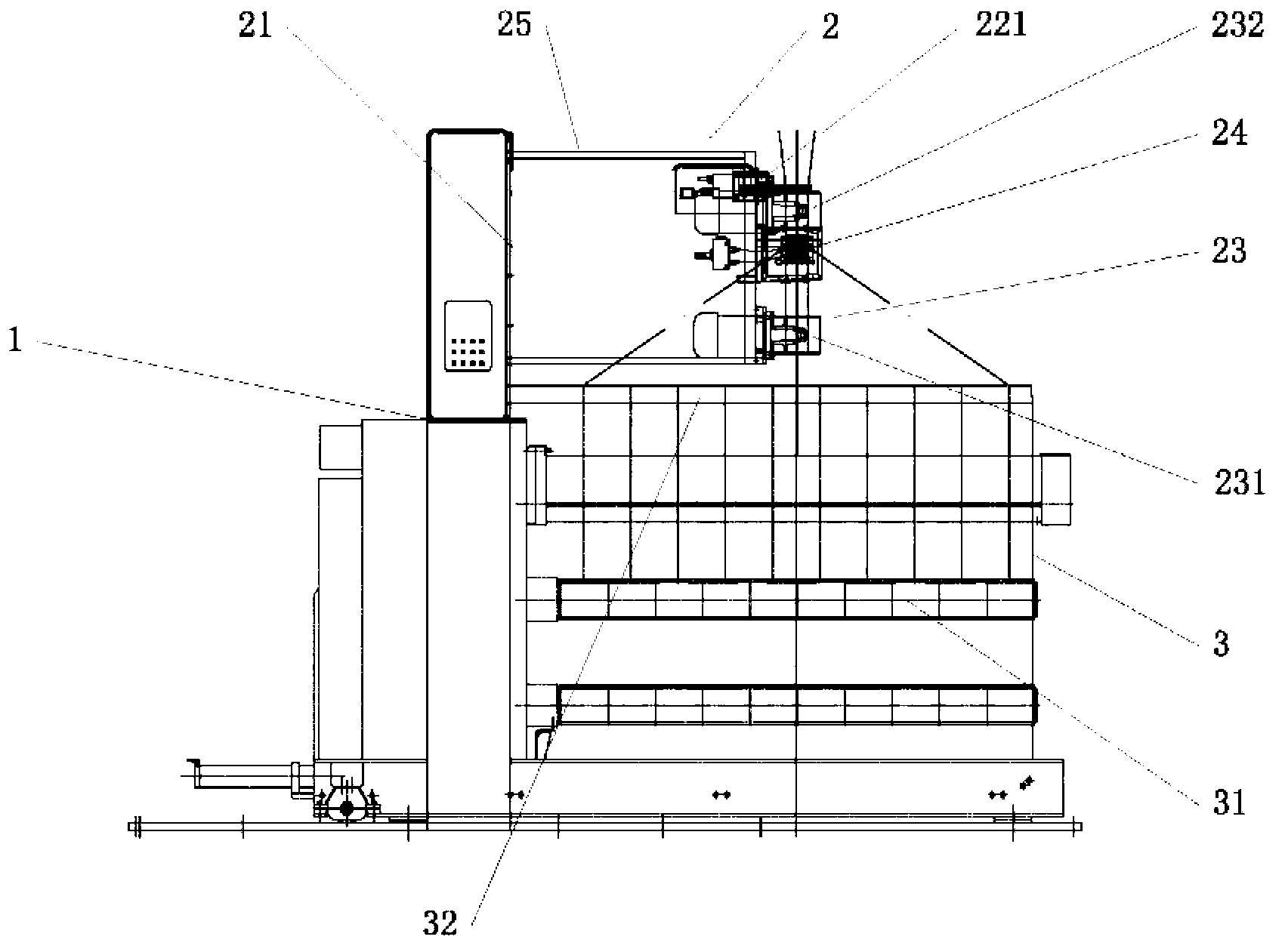
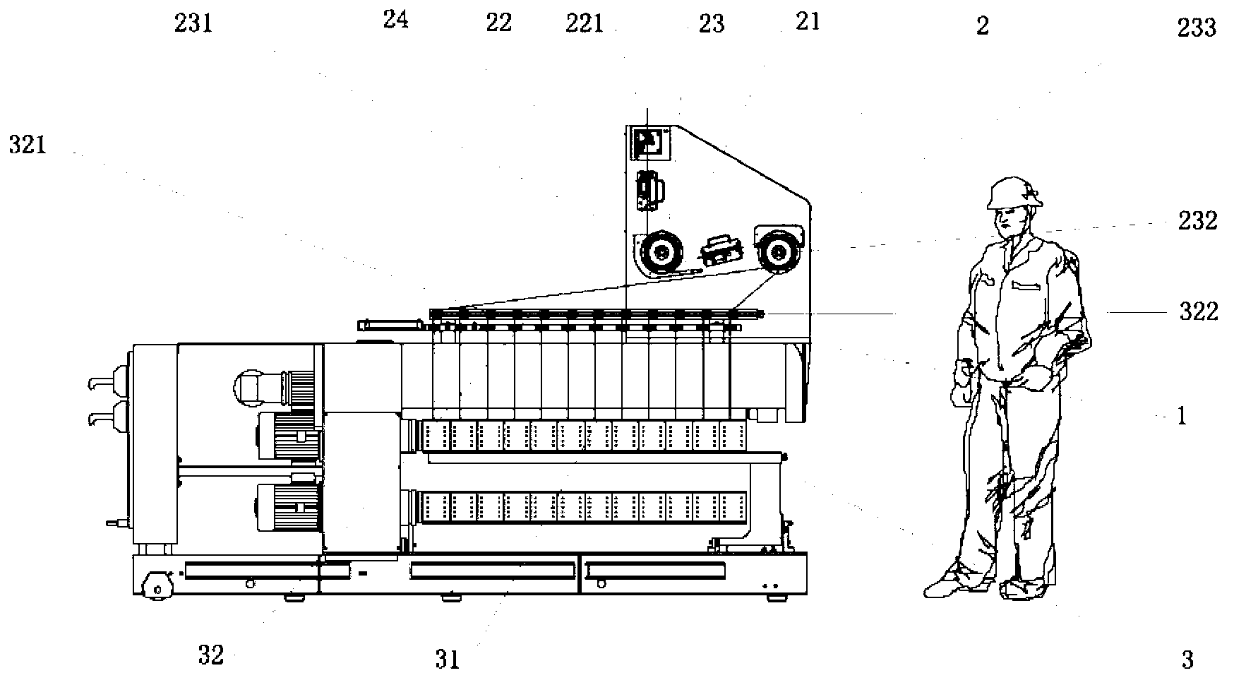
[0041] Such as figure 1 and figure 2 As shown, the POY filament drafting and winding device of the first structure provided by the embodiment of the present invention includes: a frame 1, a drafting device 2 located at the upper part of the frame 1 and a winding device 3 located at the lower part of the frame 1 . The drafting device 2 includes an installation panel 21 , a pretreatment component 22 , a drafting component 23 and a network component 24 . The pretreatment unit 22 includes a cutting and aspirating unit 221 . Of course, for the FDY filament drawing and winding device, the pretreatment component 22 also includes an oiling component. The drafting unit 23 includes a first spinning guide 231 and a second spinning guide 232 . Of course, the drafting unit 23 may also include more spinning guide discs. For the FDY filament ...


PUM


Abstract

The invention discloses a filament drawing and winding device, falling into the technical field of chemical fiber mechanical manufacturing. The device comprises a frame, a drawing apparatus located at the upper part of the frame, and a winding apparatus located at the lower part of the frame. The drawing apparatus includes a mounting panel vertically arranged at the upper part of the frame; a preprocessing part and a drawing part are sequentially distributed along the filament tow circulating direction on the mounting panel; the length directions of a filament inlet and a filament outlet of the preprocessing part are parallel to the axial direction of the drawing part; and at least one network part is arranged on the circulating path of the filament tow between the preprocessing part and the winding apparatus. The inventive device improves the filament quality, saves the labor cost for spinning, eliminates potential safety hazards, shortens the stringup time, improves the spinning production capacity, reduces stringup waste filaments, shortens the equipment mounting period, saves mounting costs, can obtain economic benefits in advance, and saves the manufacturing cost of equipment and the capital construction cost of factory building.

Description

technical field [0001] The invention relates to the technical field of chemical fiber machinery manufacturing, in particular to a filament drafting and winding device. Background technique [0002] In the prior art, the traditional drafting and winding devices for melt-spun filaments mainly include pre-orientation drafting and winding devices (POY) and full-drawing and winding devices (FDY). The stretching and winding device has been widely used for a long time in filament production enterprises all over the world. The filament drafting and winding device includes: a frame, a drafting device located at the upper part of the frame and a winding device located at the lower part of the frame The drafting device includes a mounting panel standing on the top of the frame, on which the pretreatment components (usually including oiling components and cutting and suctioning components), drafting stretching part (usually including at least two spinning guide discs or at least two se...

Claims


Application Information

Patent Timeline
Patent Type & Authority Applications(China)
IPC IPC(8): D01D7/00D01D5/16D01D13/02
Inventor 南亚芹吴寿军胡湘东吴昌木徐凯宋国亮邱军先
Owner BEIJING CHONGLEE MACHINERY ENG
Why Eureka
Try Eureka