
Cooling structure for settling chamber top of electric furnace and manufacturing method of cooling structure

A technology of cooling structure and manufacturing method, which is applied in the direction of furnace cooling devices, etc., can solve the problems of large environmental pollution, large heat loss, and agglomeration of dust bag, and achieve the effects of protecting the environment, reducing heat loss, and reducing equipment maintenance costs

Inactive Publication Date: 2012-12-26
SHAGANG GROUP
View PDF7 Cites 0 Cited by
  • Summary
  • Abstract
  • Description
  • Claims
  • Application Information

AI Technical Summary

Problems solved by technology

[0006] The purpose of the present invention is to provide a cooling structure for the roof of the settling chamber of an electric furnace and a manufacturing method thereof, which has a remarkable effect of saving energy and reducing consumption, and can solve problems such as frequent water leakage of the existing water-cooled plate, large heat loss, agglomeration of the dust bag, and large environmental pollution. have a positive effect

Method used


Image

  • Cooling structure for settling chamber top of electric furnace and manufacturing method of cooling structure
  • Cooling structure for settling chamber top of electric furnace and manufacturing method of cooling structure
  • Cooling structure for settling chamber top of electric furnace and manufacturing method of cooling structure

Examples


Embodiment Construction

[0026] refer to figure 1 It is a preferred embodiment of the present invention, and the cooling structure of the roof of the electric furnace settling chamber includes a water cooling plate 200 on the roof of the settling chamber and a plurality of rivets fixedly connected to the bottom surface of the water cooling plate on the roof of the settling chamber. The space is fixed and connected as a whole by a diamond-shaped steel mesh 203, and at the same time, the rivets and the diamond-shaped steel mesh are covered with a heat-insulating coating 205.

[0027] As one of the preferred solutions, the rivet adopts a V-shaped rivet 204, which is welded and fixed on the bottom surface of the water-cooled plate on the top of the settling chamber.

[0028] As one of the preferred solutions, the rivet is welded and fixed with the diamond-shaped steel mesh to form a whole.

[0029] As one of the preferred solutions, the thickness of the diamond-shaped expanded metal is more than 6 mm. ...


PUM

PropertyMeasurementUnit
Thicknessaaaaaaaaaa
Thicknessaaaaaaaaaa

Abstract

The invention discloses a cooling structure for the settling chamber top of an electric furnace and a manufacturing method of the cooling structure. The aim of cooling the settling chamber top is fulfilled by hanging a stainless steel top and spraying. The technical scheme of the invention is specifically as follows: a plurality of riveting pieces are fixedly connected on the bottom surface of a water cooling plate on the settling chamber top, and are fixedly connected into a whole through a diamond-shaped steel plate net; heat insulating coatings are coated on the riveting pieces and the diamond-shaped steel plate net; the riveting pieces are preferably fixed with the bottom surface of the water cooling plate on the settling chamber top and the diamond-shaped steel plate net in a welding way; moreover, the riveting pieces are preferably V-shaped riveting pieces; the thickness of the diamond-shaped steel plate net is preferably over 6 millimeters; and the thicknesses of the heat insulating coatings are preferably over 50 millimeters. Due to the adoption of the cooling structure, the conventional tubular water cooling plate is eliminated, the defects of easy water leakage, easy agglomerating of a dust-removing cloth bag, large heat loss, high equipment maintenance cost and the like existing in the prior art are overcome, the residual heat recovering effect and the dust-removing effect can be improved effectively, environmental friendliness is facilitated, and the equipment maintenance cost can be reduced greatly.

Description

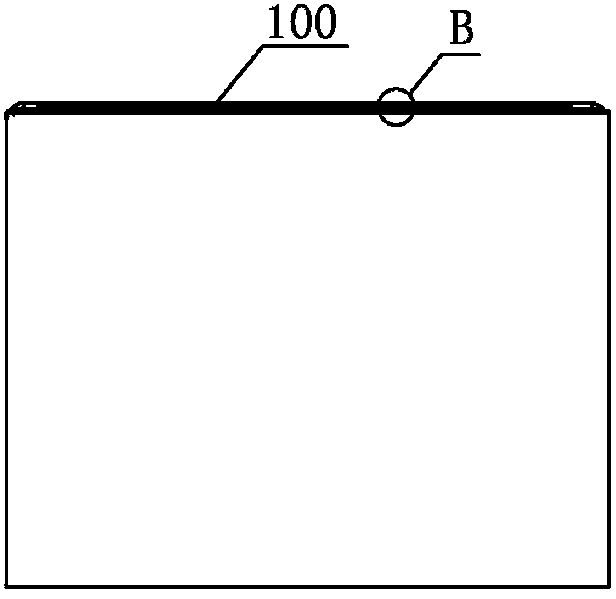
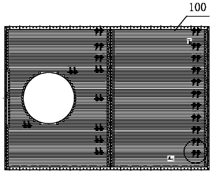
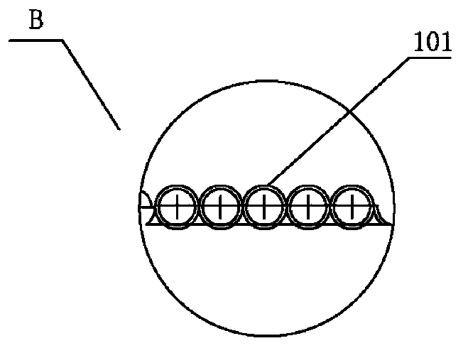
technical field [0001] The invention particularly relates to a roof cooling structure of an electric furnace settling chamber with the characteristics of energy saving and consumption reduction and a manufacturing method thereof, belonging to the field of iron and steel metallurgy. Background technique [0002] The water-cooled plate on the roof of the traditional electric furnace settling chamber (hereinafter referred to as the water-cooled plate) is generally a tubular water-cooled plate 100, see Figure 1-Figure 3 , which usually have the following drawbacks: [0003] (1) The maintenance space is generally only 500mm. One side is the electric furnace equipment and reinforced concrete platform, and the other side is the dust removal and flue gas waste heat recovery system. It is extremely inconvenient to replace the conventional water-cooled plate with a size of about 12.6×8.5m and cannot be hoisted. Lifting in and out for replacement; [0004] (2) The cooling effect of t...

Claims


Application Information

Patent Timeline
IPC IPC(8): F27D1/12
Inventor 曹斌张新科
Owner SHAGANG GROUP
Learn More