
Imaging lens, camera device and portable information terminal device

A technology of imaging lens and imaging magnification, which is applied in the fields of imaging lens, camera device and portable information terminal, and can solve problems such as dispersion, unfavorable operability due to changes in the overall length of the lens system, and shadow generation

Active Publication Date: 2012-12-26
RICOH KK
View PDF8 Cites 6 Cited by
  • Summary
  • Abstract
  • Description
  • Claims
  • Application Information

AI Technical Summary

Problems solved by technology

[0008] Although the imaging lenses disclosed in Patent Documents 1 and 2 are large-aperture lenses, the exit pupil position is close to the image plane, and if the size of the solid-state imaging device CCD or CMOS for imaging is considered, shadows may occur
[0009] The imaging lens disclosed in Patent Document 3 is relatively bright, with an F value of 1.9, and has advantages in large apertures. However, the overall length of the lens is more than nine times the maximum image height, so further improvement in miniaturization is required.
[0010] On the other hand, the front lens group protruding method imaging lens system in which the optical total length changes during focusing reduces aberration fluctuations by protruding the lens group to change the interval between the lens groups, but the change in the total length of the lens system is not conducive to operability , so the operation of this lens is relatively complicated
[0011] However, in the internal focusing imaging lens system with fixed front lens group during focusing, the aberration will change during focusing, especially at close distances, it is prone to astigmatism or astigmatic difference

Method used


Image

  • Imaging lens, camera device and portable information terminal device
  • Imaging lens, camera device and portable information terminal device
  • Imaging lens, camera device and portable information terminal device

Examples


Embodiment 1

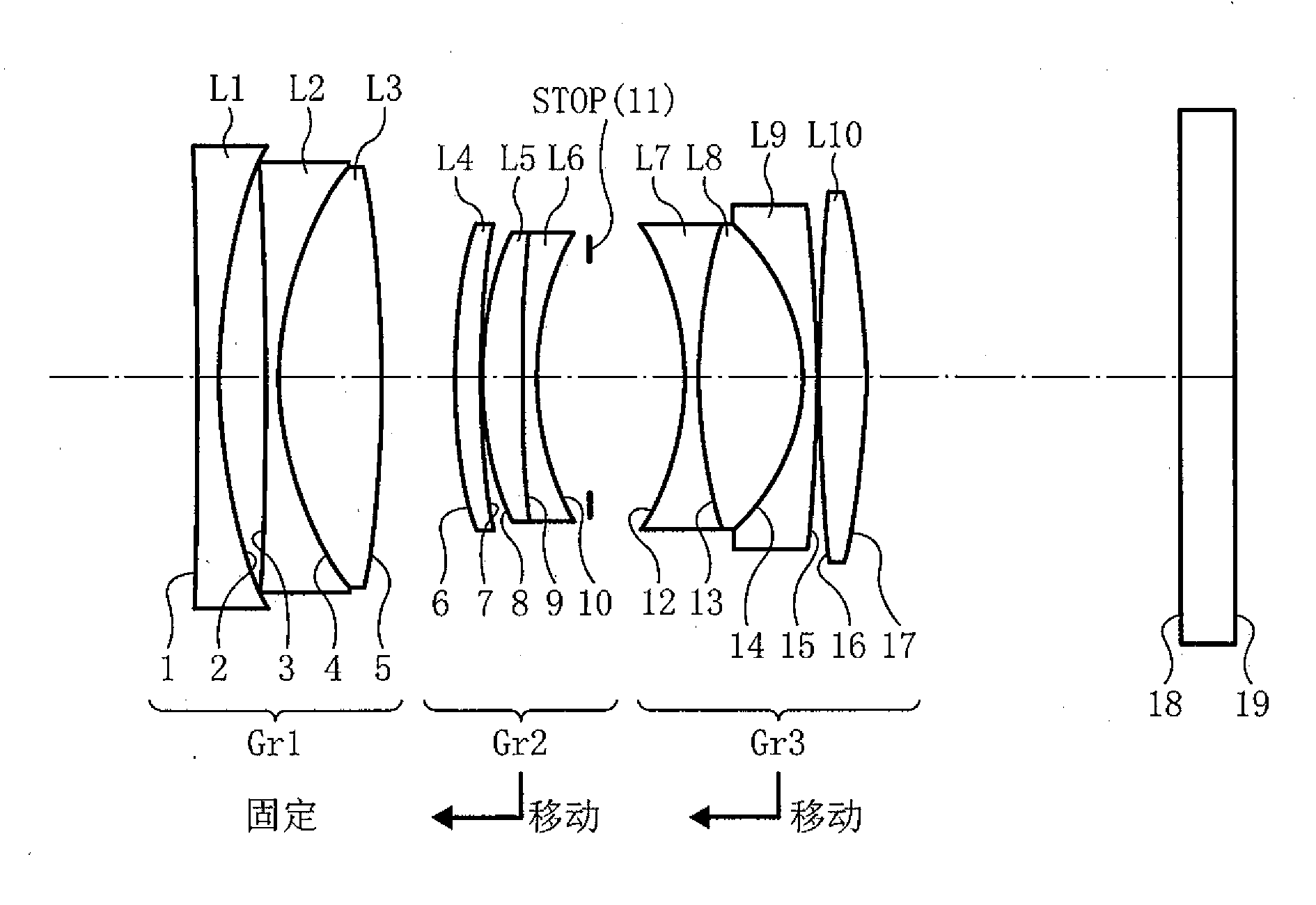
[0162] The imaging lens of embodiment 1 is as figure 1 shown.

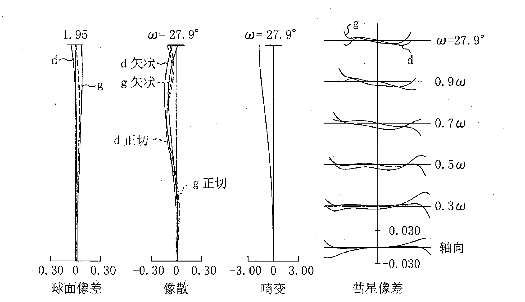
[0163] F=27.0mm, Fno=1.95, the data of Example 1 are shown in Table 1.

[0164] Table 1

[0165]

R

D

N d

v d

1

-375.788

1.20

1.8211

24.1

2*

34.894

2.58

3

-209.543

0.80

1.5163

64.1

4

18.506

5.78

1.8348

42.7

5

-64.736

D 5

6

29.487

1.48

1.8503

32.3

7

45.537

0.10

8

19.390

2.30

1.8348

42.7

9

119.373

0.80

1.5955

39.2

10

15.751

D 10

11

INF

5.44

12

-15.218

0.80

1.6889

31.1

13

26.323

5.87

1.8348

42.7

14

-10.771

0.80

1.6889

31.1

15

-77.815

...

Embodiment 2

[0190] The imaging lens of embodiment 2 is as Figure 5 shown.

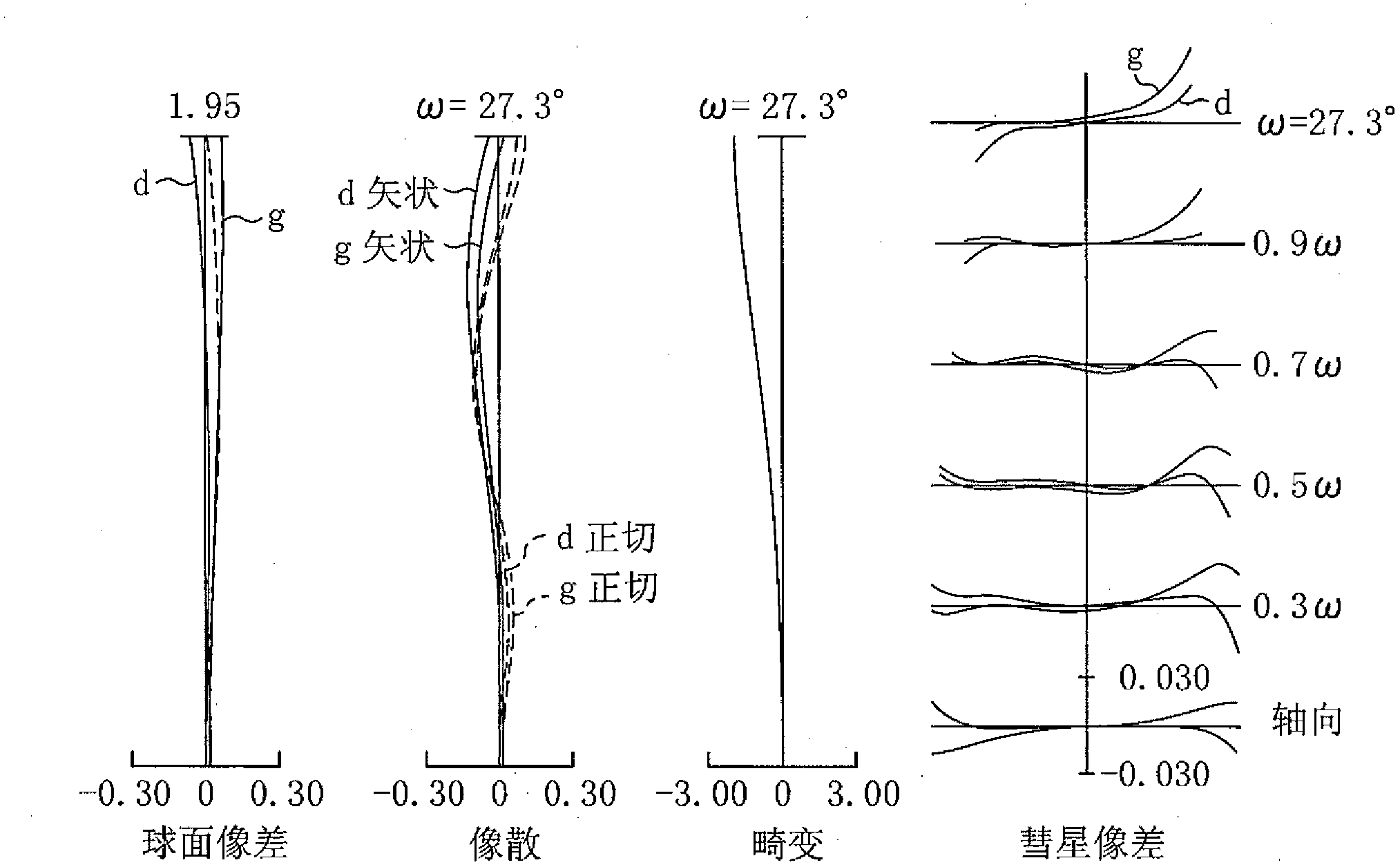
[0191] F=27.0mm, Fno=1.94, the data of Example 1 are shown in Table 4.

[0192] Table 4

[0193]

R

D

N d

v d

1

-56.022

1.20

1.8211

24.1

2*

51.132

2.15

3

-217.546

0.80

1.5163

64.1

4

20.757

5.76

1.8348

42.7

5

-44.272

D 5

6

36.328

1.60

1.8503

32.3

7

76.700

0.10

8

19.298

2.42

1.8348

42.7

9

-3301.909

0.80

1.5955

39.2

10

15.403

2.84

11

INF

D11

12

-17.852

0.81

1.6889

31.1

13

19.376

7.78

1.8348

42.7

14

-11.925

0.81

1.6889

31.1

15

280.357

...

Embodiment 3

[0217] The imaging lens of embodiment 3 is as Figure 9 shown.

[0218] F=27.0mm, Fno=1.95, the data of Example 3 are shown in Table 7.

[0219] Table 7

[0220]

R

D

N d

v d

1

-55.285

1.20

1.8211

24.1

2*

51.045

1.94

3

-237.905

0.85

1.5163

64.1

4

20.699

5.86

1.8348

42.7

5

-44.565

D5

6

35.531

1.60

1.8503

32.3

7

72.180

0.23

8

19.512

2.30

1.8348

42.7

9

-1102.964

0.83

1.5955

39.2

10

15.543

2.82

11

INF

D 11

12

-17.940

0.82

1.6889

31.1

13

19.392

7.82

1.8348

42.7

14

-12.112

0.80

1.6889

31.1

15

235.496

...


PUM


Abstract

The invention relates to an imaging lens, a camera device and a portable information terminal device, which can be used to provide an emitting-out pupil far away from the image surface, and is provided with a large-caliber small-sized high performance fixing imaging lens. The imaging lens is provided, from object side to image side, a first lens group (GR1) having the positive refraction ability or the negative refraction ability, a second lens group (GR2) having the positive refraction ability, and a third lens group (GR3) having the positive refraction ability. An aperture (Stop) is disposed between the second lens group and the image surface. The focusing can be realized by fixing the first lens group and moving the second lens group and the third lens group along the optical axis, and the condition can be satisfied, the F2 / F3 is less than 1.6 and larger than 0.5, the IFI / F is less than 20.0 and larger than 6.0, wherein the F is the focal length of the whole system of the imaging device by the infinity sharp focus, the F1, the F2, and the F3 are respectively the focal lengths of the first length group, the second length group, and the third length group.

Description

technical field [0001] The present invention relates to an imaging lens, a camera device and a portable information terminal. Background technique [0002] In recent years, imaging devices such as digital still cameras and digital video recorders using solid-state imaging elements such as CCDs and CMOSs ​​have become popular. Among them, digital still cameras have become popular as imaging devices replacing silver halide cameras. [0003] With the increasing number of pixels of solid-state imaging devices in imaging devices, it is required to further improve the optical performance of imaging lenses as imaging lenses. On the other hand, from the viewpoint of portability, the imaging device is required to be compact while having high performance. [0004] Furthermore, as the imaging speed increases, the imaging lens is required to be brighter. [0005] Regarding the angle of view of the camera lens of a digital camera, the currently popular angle of view is suitable for cas...

Claims


Application Information

Patent Timeline
Patent Type & Authority Applications(China)
IPC IPC(8): G02B13/00G02B13/18
Inventor 窪田高士
Owner RICOH KK
Learn More