Automatic focusing method for digital optical imaging system based on bilateral forecasting intersection

A technology of digital optics and imaging system, applied in the direction of optics, optical components, TV system components, etc., can solve the problems of long lens movement distance, susceptibility to noise interference, principle error, etc., to avoid swing search process, The effect of high focusing efficiency and reduced calculation times

Active Publication Date: 2012-12-26
CHONGQING UNIV
View PDF9 Cites 3 Cited by
  • Summary
  • Abstract
  • Description
  • Claims
  • Application Information

AI Technical Summary

Problems solved by technology

The binary search method and the Fibonacci search method have disadvantages such as being susceptible to noise interference, the lens moving distance is too long, and the reciprocating motion of the moving microscope actuator repeatedly introduces space-back errors, which limits their practical application.
Most of the automatic focusing methods based on curve fitting assume that the asymmetric actual focusing evaluation function curve is symmetrical about the peak position, which will introduce a principle error

Method used


Image

  • Automatic focusing method for digital optical imaging system based on bilateral forecasting intersection
  • Automatic focusing method for digital optical imaging system based on bilateral forecasting intersection
  • Automatic focusing method for digital optical imaging system based on bilateral forecasting intersection

Examples


Embodiment 1

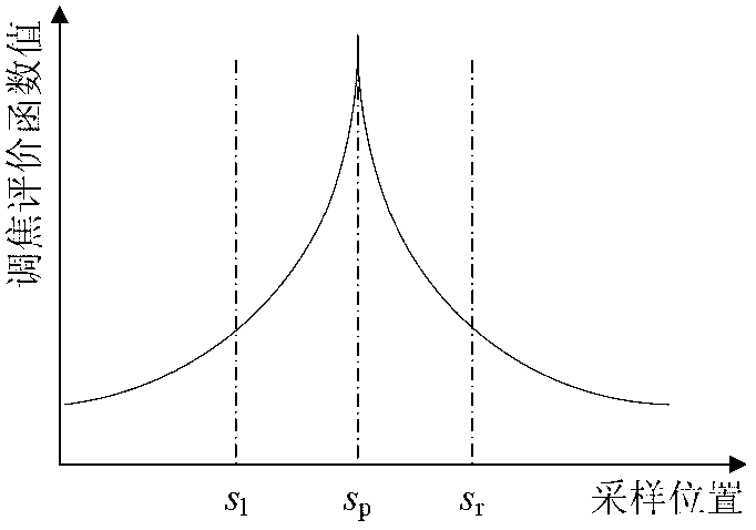
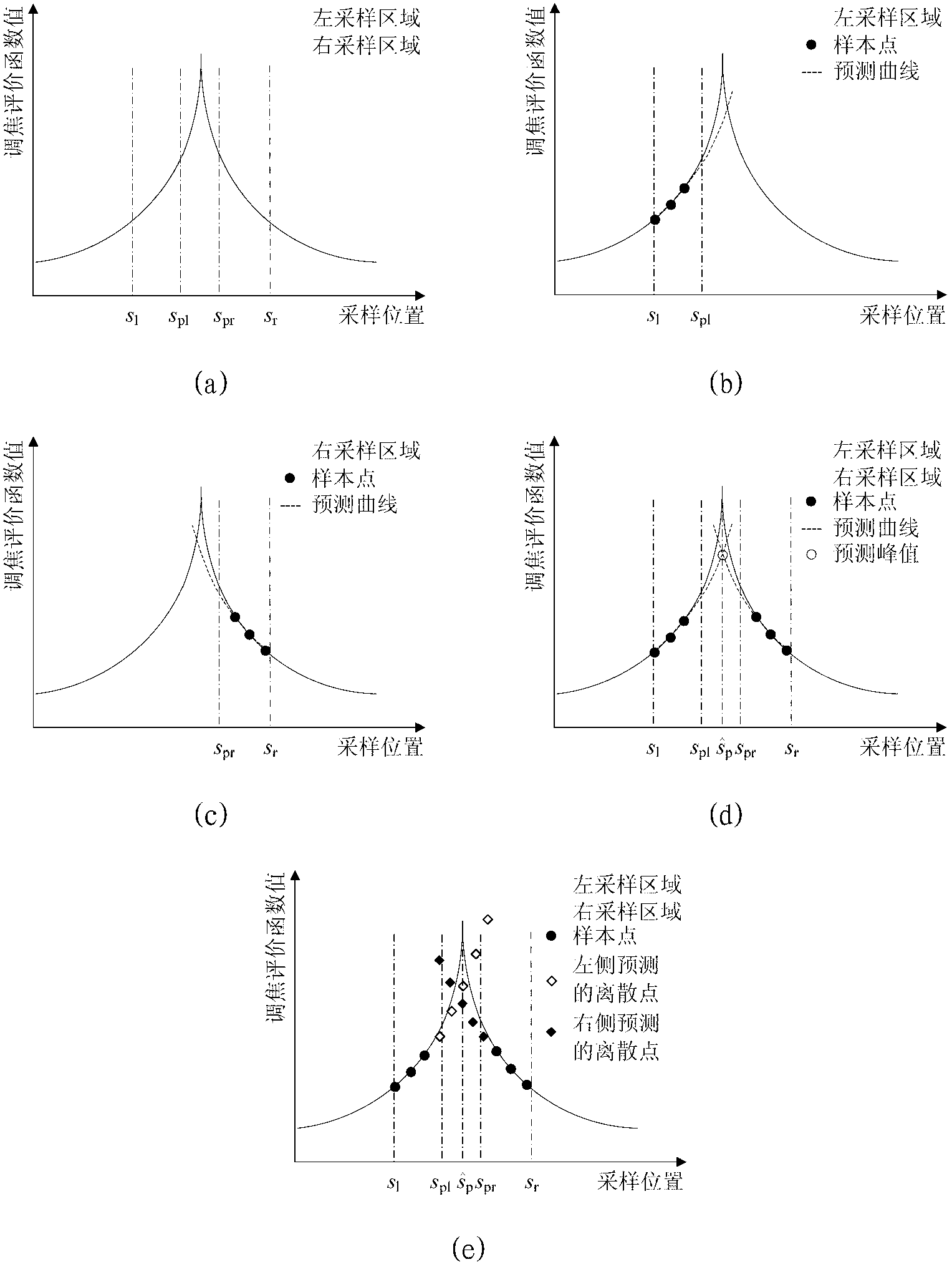
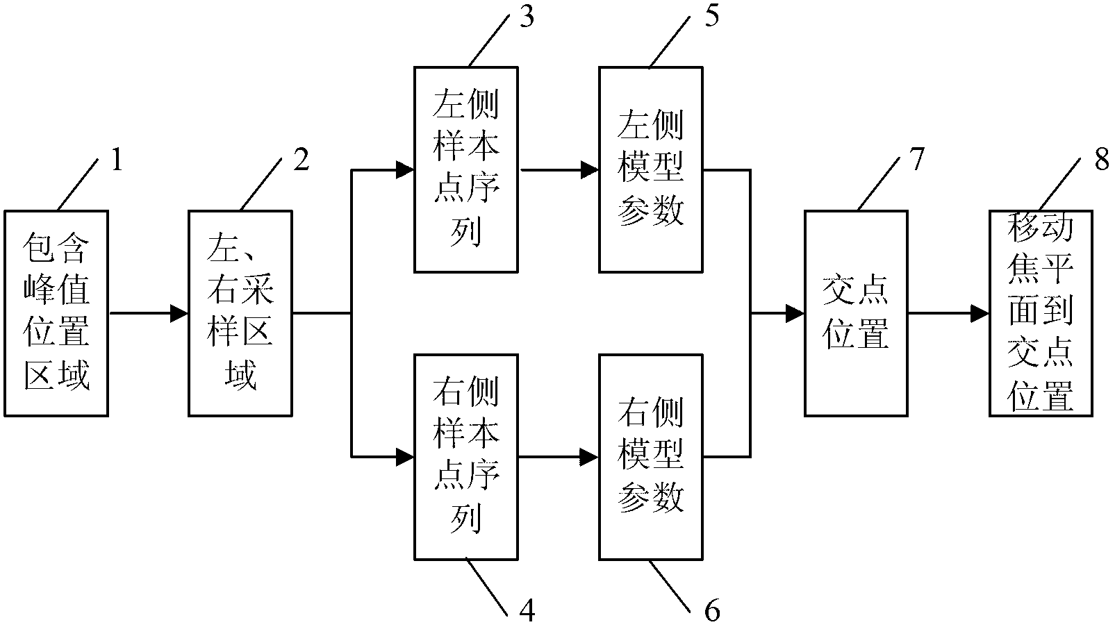
[0059] refer to image 3 , the flow chart of the digital optical imaging system automatic focusing method method based on bilateral prediction and intersection of this embodiment, including determining the peak position area (1), left and right sampling areas (2), and obtaining the left sample point sequence (3) Sample point sequence on the right (4), model parameters on the left (5), model parameters on the right (6), intersection position (7), and moving the focal plane to the intersection position (8). To illustrate the specific implementation of this embodiment, the Variance function is used as the focusing evaluation function, the 7-point hill-climbing method is used as a method for determining the area containing the peak position of the focusing evaluation function curve and the left and right sampling areas, and the exponential prediction model is used as the bilateral prediction model, least squares as the method for computing model parameters for a two-sided predicti...

specific Embodiment 2

[0081] refer to Figure 5 , the implementation module diagram of the bilateral predictive intersection auto-focusing method in this embodiment includes the area (1) including the peak position, the left and right sampling areas (2), the left sample point sequence (3), and the right sample point Sequence (4), Sequence of discrete points on the left (9), Sequence of discrete points on the right (10), Sequence The position corresponding to the minimum value in (11) and move the focal plane to the minimum value position (12). The difference between this embodiment and embodiment 1 is that (9) and (10) in this embodiment are all the discrete point sequences of calculation prediction rather than the model parameters (5) and ( 6), the difference between this embodiment and embodiment 1 is that what needs to be obtained in this embodiment is the sequence The minimum value position (11) is not the intersection position (7) of the predicted left and right focusing evaluation functio...

specific Embodiment 3

[0082] refer to Image 6 , the implementation block diagram of the bilateral prediction intersection auto-focusing method in this embodiment includes the area (1) including the peak position, the left and right sampling areas (2), the left sample point sequence (3), and the left model parameters (5), right sample point sequence (4), right model parameters (6), intersection position (7) and moving the focal plane to the intersection position (8). The difference between this embodiment and Embodiment 1 is that in this embodiment, after the left and right sampling areas (2) are determined. It is not possible to directly obtain the left and right sample point sequences from the data obtained in the process of determining the area containing the peak position (1) and determining the left and right sampling areas (2), but it is necessary to sample in the left and right sampling areas respectively. Get the left and right sample point data.


PUM


Abstract

The invention relates to an automatic focusing method for a digital optical imaging system, which comprises the following steps of: independently sampling and forecasting focusing evaluation function curves on left and right sides in the positions of focusing evaluation function curve peaks; calculating the position of an intersection point of the forecast left and right focusing evaluation function curves or a minimum value of an absolute value of a difference of the focusing evaluation function values in the same positions in the forecast left and right disperse focusing evaluation function value sequences; and controlling an executing mechanism to move a focal plane of the digital optical imaging system to the intersection point or minimum value position (focusing position). According to the automatic focusing method provided by the invention, independent sampling and forecasting are performed on left and right adjacent regions containing the peak position areas; a principle error caused by taking actually asymmetrical focusing evaluation function curves as symmetrical curves according to the automatic focusing method based on curve fitting and a swinging search process possibly occurring nearby the peaks according to a quick climbing method are avoided; the influence of sampling step length on the focusing precision according to the automatic focusing method based on bilateral forecasting intersection is small and the focusing precision and speed are higher.

Description

technical field [0001] The invention relates to the technical field of automatic control, in particular to an automatic focusing method for a digital optical imaging system. Background technique [0002] In recent years, with the development and progress of electronic technology and computer technology, especially the maturity and application of digital imaging device manufacturing technologies such as CCD and CMOS, digital optical imaging systems have been widely used in human life and scientific research. Among the many technologies of the digital optical imaging system, the automatic focusing method is one of the key technologies that affect the imaging quality and efficiency of the digital optical imaging system. Auto-focus technology can generally be divided into active auto-focus method and passive auto-focus method. The active auto-focus method requires additional optical path or distance measuring equipment, resulting in complex system and high cost. The passive au...

Claims


Application Information

Patent Timeline
Patent Type & Authority Applications(China)
IPC IPC(8): G03B13/36G02B7/36H04N5/232
Inventor 王代华周锋吴朝明
Owner CHONGQING UNIV
Why Eureka
Try Eureka