Automatic focusing method for digital optical imaging system based on bilateral forecasting intersection
A technology of digital optics and imaging system, applied in the direction of optics, optical components, TV system components, etc., can solve the problems of long lens movement distance, susceptibility to noise interference, principle error, etc., to avoid swing search process, The effect of high focusing efficiency and reduced calculation times
- Summary
- Abstract
- Description
- Claims
- Application Information
AI Technical Summary
Problems solved by technology
Method used
Image
Examples
Embodiment 1
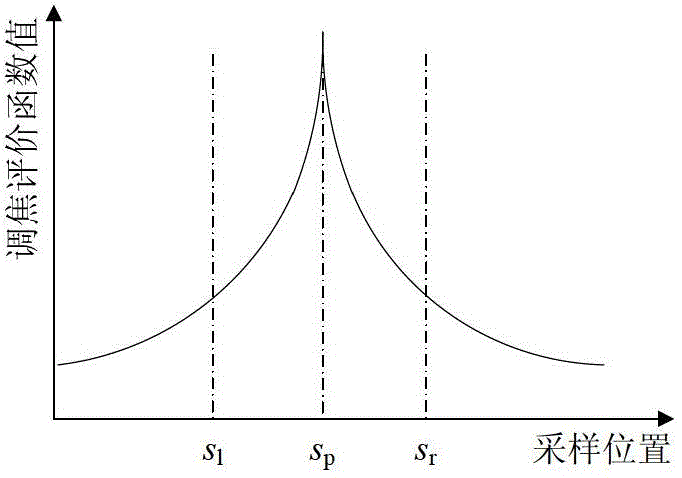
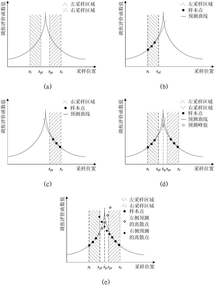
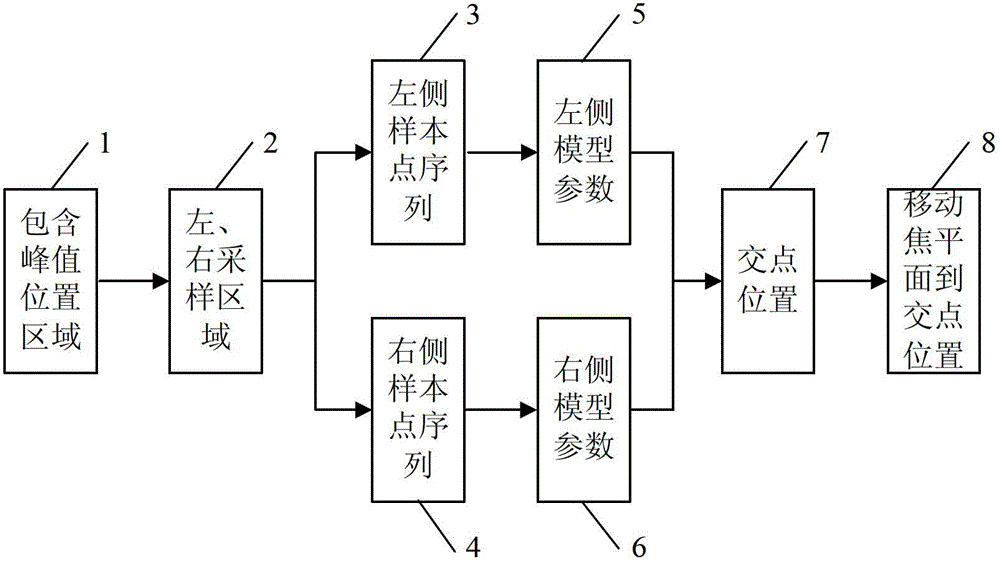
[0059] refer to image 3 , the flow chart of the digital optical imaging system automatic focusing method method based on bilateral prediction and intersection of this embodiment, including determining the peak position area (1), left and right sampling areas (2), and obtaining the left sample point sequence (3) Sample point sequence on the right (4), model parameters on the left (5), model parameters on the right (6), intersection position (7), and moving the focal plane to the intersection position (8). To illustrate the specific implementation of this embodiment, the Variance function is used as the focusing evaluation function, the 7-point hill-climbing method is used as a method for determining the area containing the peak position of the focusing evaluation function curve and the left and right sampling areas, and the exponential prediction model is used as the bilateral prediction model, least squares as the method for computing model parameters for a two-sided predicti...
specific Embodiment 2
[0081] refer to Figure 5 , the implementation module diagram of the bilateral predictive intersection auto-focusing method in this embodiment includes the area (1) including the peak position, the left and right sampling area (2), the left sample point sequence (3), and the right sample point Sequence (4), Sequence of discrete points on the left (9), Sequence of discrete points on the right (10), Sequence The position corresponding to the minimum value in (11) and move the focal plane to the minimum value position (12). The difference between this embodiment and embodiment 1 is that (9) and (10) in this embodiment are all the discrete point sequences of calculation prediction rather than the model parameters (5) and ( 6), the difference between this embodiment and embodiment 1 is that what needs to be obtained in this embodiment is the sequence The minimum value position (11) is not the intersection position (7) of the predicted left and right focusing evaluation function...
specific Embodiment 3
[0082] refer to Image 6 , the implementation module diagram of the bilateral predictive intersection auto-focusing method in this embodiment includes the area (1) including the peak position, the left and right sampling areas (2), the left sample point sequence (3), and the left model parameters (5), right sample point sequence (4), right model parameters (6), intersection position (7) and moving the focal plane to the intersection position (8). The difference between this embodiment and Embodiment 1 is that in this embodiment, after the left and right sampling areas (2) are determined. It is not possible to directly obtain the left and right sample point sequences from the data obtained in the process of determining the area containing the peak position (1) and determining the left and right sampling areas (2), but it is necessary to sample in the left and right sampling areas respectively. Get the left and right sample point data.
PUM
 Abstract
Description
Claims
Application Information
 - R&D
- Intellectual Property
- Life Sciences
- Materials
- Tech Scout
- Unparalleled Data Quality
- Higher Quality Content
- 60% Fewer Hallucinations
Browse by: Latest US Patents, China's latest patents, Technical Efficacy Thesaurus, Application Domain, Technology Topic, Popular Technical Reports.
© 2025 PatSnap. All rights reserved.Legal|Privacy policy|Modern Slavery Act Transparency Statement|Sitemap|About US| Contact US: help@patsnap.com


