Movable high-voltage high-capacity chained STATCOM system container structure

A container and large-capacity technology, applied in system integration technology, information technology support system, flexible AC power transmission system, etc., can solve the inconvenience of chain STATCOM in power expansion and safe operation, inconvenience in mass production, installation, commissioning and maintenance of STATCOM. To meet the requirements of large-capacity installations, facilitate long-distance transportation, and ensure accuracy

Active Publication Date: 2012-12-26
GUANGDONG POWER GRID CO LTD DONGGUAN POWER SUPPLY BUREAU +1
View PDF5 Cites 4 Cited by
  • Summary
  • Abstract
  • Description
  • Claims
  • Application Information

AI Technical Summary

Problems solved by technology

[0006] In the existing technology, the STATCOM system structure is a small frame structure, or a control cabinet, which is placed inside the machine room, which is expensive and requires secondary heat dissipation
[0007] In addition, the power units in the prior art are all assembled on-site by the frame, without a modular structure, which is inconvenient for mass production of STATCOMs with different voltages and capacities, which makes installation, commissioning, and maintenance inconvenient
[0008] Also, in the prior art, chained STATCOMs are not convenient for power expansion and safe operation
[0009] In the existing technology, there is still a lack of chained STATCOMs using IEGT high-voltage and high-power devices, 35kV high voltage, and ±200Mvar large capacity.

Method used


Image

  • Movable high-voltage high-capacity chained STATCOM system container structure
  • Movable high-voltage high-capacity chained STATCOM system container structure
  • Movable high-voltage high-capacity chained STATCOM system container structure

Examples


Embodiment Construction

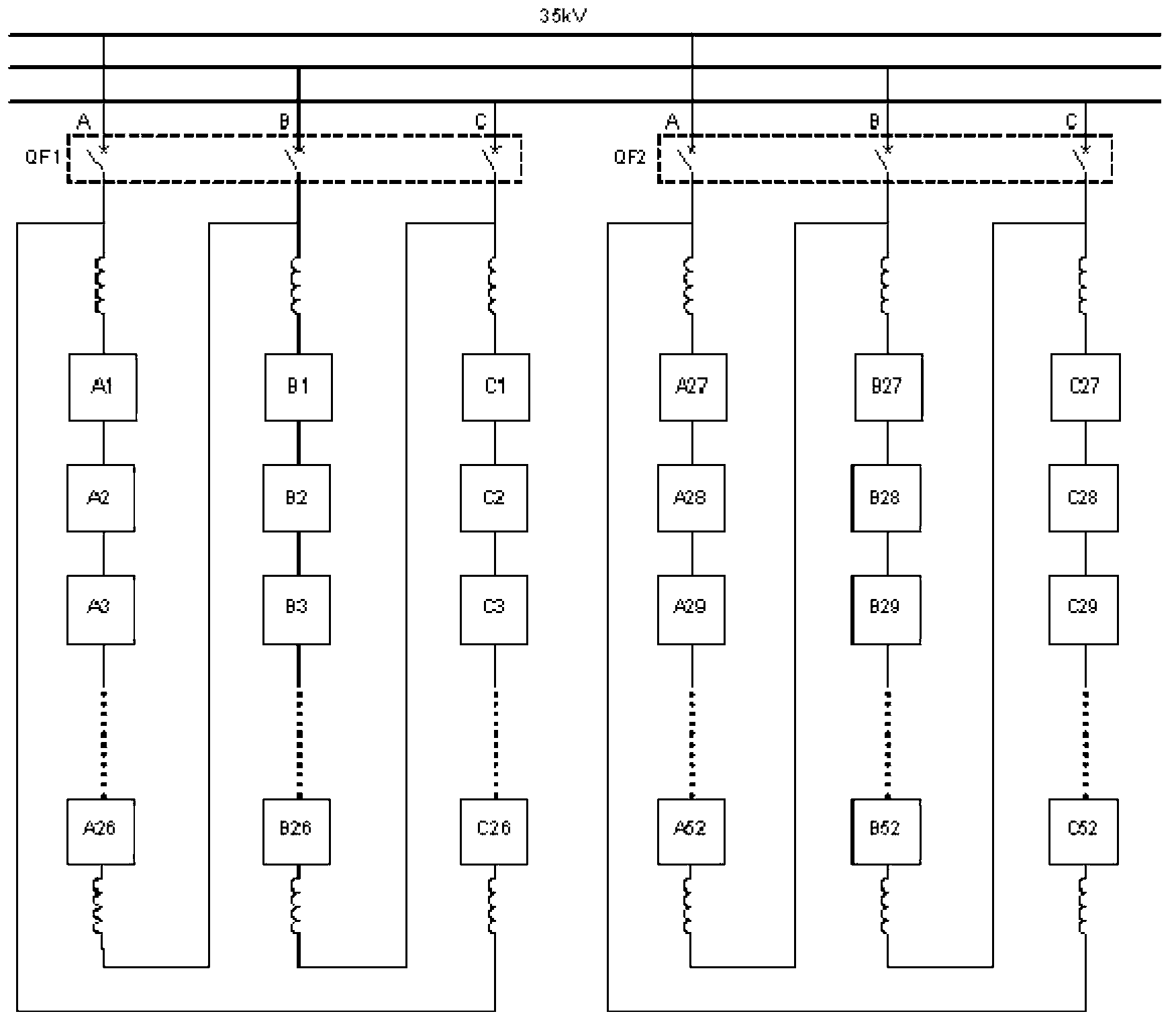
[0044] Such as Figure 1 to Figure 7 ,as well as Figure 12 As shown, the movable 35kV ± 200Mvar chained STATCOM dual-machine parallel system of the present invention includes:

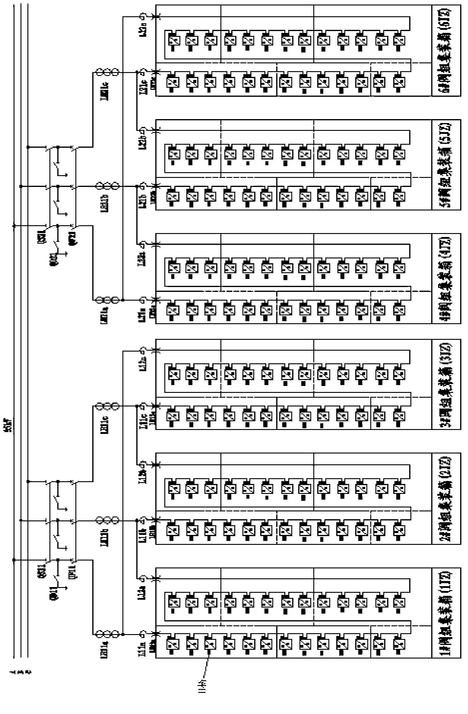
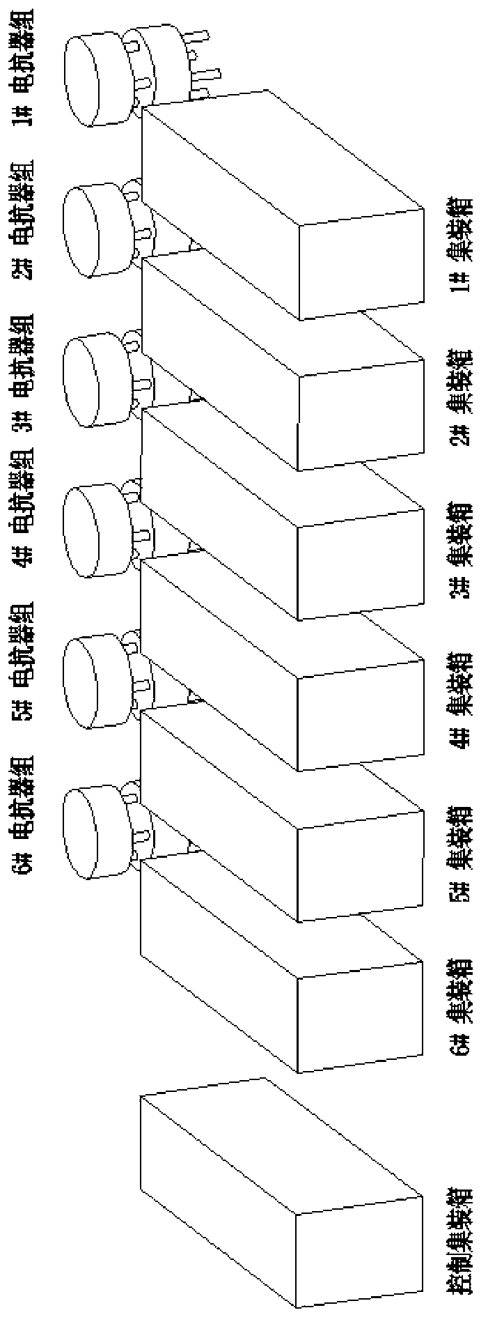
[0045] Two chained STATCOM systems connected in parallel, each chained STATCOM system consisting of three-phase chained H-bridge power cell groups, see figure 1 and figure 2 , each phase-chained H-bridge power unit group includes 26 H-bridge power units in series plus a reactor at each end, each phase-chained H-bridge power unit group is placed in a valve group container, six identical Converter containers 1﹟~6﹟ are arranged in sequence outdoors, and the two reactors of each phase chain H-bridge power unit group are placed up and down and placed outside the container (see image 3 ), the two parallel chained STATCOM systems can be directly connected to the 35kV power grid through two high-voltage switches QF1 and QF2 respectively. figure 1 and figure 2 .

[0046] see Figure 5 One side of the...


PUM


Abstract

A movable high-voltage high-capacity chained STATCOM system container structure comprises two chained STATCOM systems which are connected in parallel, each system comprises a three-phrase chained H bridge power unit group, and each three-phrase chained H bridge power unit group comprises a plurality of H bridge power units which are connected in series. Two ends of the each three-phrase chained H bridge power unit group are respectively provided with an electric reactor, and the each three-phrase chained H bridge power unit group is installed in a valve group container. The two electric reactors of the each three-phrase chained H bridge power unit group are placed up and down, and arranged outside the valve group container. The two systems which are connected in parallel are directly hung into a 35 kilovolt power grid respectively through a high-voltage switch QF1 and a high-voltage switch QF2. The total number of chained STATCOM system containers is seven. In the seven chained STATCOM system containers, six chained STATCOM system containers are valve group containers and one chained STATCOM system container is a controlling container. The movable high-voltage high-capacity chained STATCOM system container structure is low in manufacturing cost and good in heat dissipation, and brings convenience to mass production of STATCOM with different voltages and different capacities. In addition, the movable high-voltage high-capacity chained STATCOM system container structure is compact in structure, convenient to install, adjust, maintain, disassemble and transport, simple to place and install in the open air, convenient for power expansion and safe operation, and capable of satisfying the requirement of high-capacity installation.

Description

technical field [0001] The invention relates to a chain-type static synchronous compensator (STATCOM) system structure, in particular to a movable container-type 35kV±200Mvar chain-type STATCOM dual-machine parallel system structure. Background technique [0002] With the development of social economy and the improvement of people's living standards, the demand for electric energy is increasing day by day, the capacity and output of power generation equipment are constantly increasing, and the scope of power supply is also correspondingly expanded, and it is gradually developing into a large-scale combined power system. In order to meet the increasing demand for electric energy, many new changes have taken place in the power system, for example, the increase of the voltage level of the power grid, the interconnection of the power system, the widespread application of large-capacity generator sets, hydropower plants, pit mouth power plants, and nuclear power plants far away fr...

Claims


Application Information

Patent Timeline
Patent Type & Authority Applications(China)
IPC IPC(8): H02B1/56H02J3/18H02J13/00
CPCY04S10/22Y02E40/16Y02E40/74Y02E40/10Y02E40/70
Inventor 魏远航钟连宏陈剑光欧阳旭东雷烈波李春华谢化安罗瑞彬黄伟雄何伟斌高明振曾伟忠张汉光王春岩白羽
Owner GUANGDONG POWER GRID CO LTD DONGGUAN POWER SUPPLY BUREAU
Why Eureka
Try Eureka