Slag removing drum screen capable of distributing pulp

A cylinder screen and slurry technology, which is applied in the direction of filter screen, solid separation, grid, etc., can solve the problems of limited effective use area of ​​slag removal screen, large particles of waste slag cannot be removed, unfavorable ore discharge, etc., so as to save the floor space of the plant Size, protection of operating equipment, and the effect of saving the height difference of the factory building

Active Publication Date: 2013-01-02
MCC NORTH (DALIAN) ENG TECH CO LTD
View PDF5 Cites 3 Cited by
  • Summary
  • Abstract
  • Description
  • Claims
  • Application Information

AI Technical Summary

Problems solved by technology

Using a flat-plate slag removal screen, due to the use of ore feeding pipes, the effective area of ​​the slag removal screen is limited, and manual slag removal is often required; while the currently used cylindrical slag removal screen needs to be washed and cleaned with water once the sieve holes are blocked by waste slag. Slag discharge after sieving is not conducive to ore discharge, and some large-grained waste residues cannot be removed by the above method
In addition, the current flat-ring strong magnetic machine and vertical ring strong magnetic machine generally use two pipes to feed the ore. It is necessary to arrange a separate two-pipe pulp distributor before feeding each flat-ring strong magnetic machine and vertical ring strong magnetic machine. The distributor needs to be set at a position higher than the feeding port of the flat ring strong magnetic machine and the vertical ring strong magnetic machine, so that the slurry can flow from the slurry distributor into the flat ring strong magnetic machine and the vertical ring strong magnetic machine, which not only occupies the height difference of the plant , and it is also necessary to reserve a plane position for the slurry distributor

Method used


Image

  • Slag removing drum screen capable of distributing pulp
  • Slag removing drum screen capable of distributing pulp
  • Slag removing drum screen capable of distributing pulp

Examples


Embodiment Construction

[0020] The specific implementation manner of the present invention will be further described below in conjunction with the accompanying drawings.

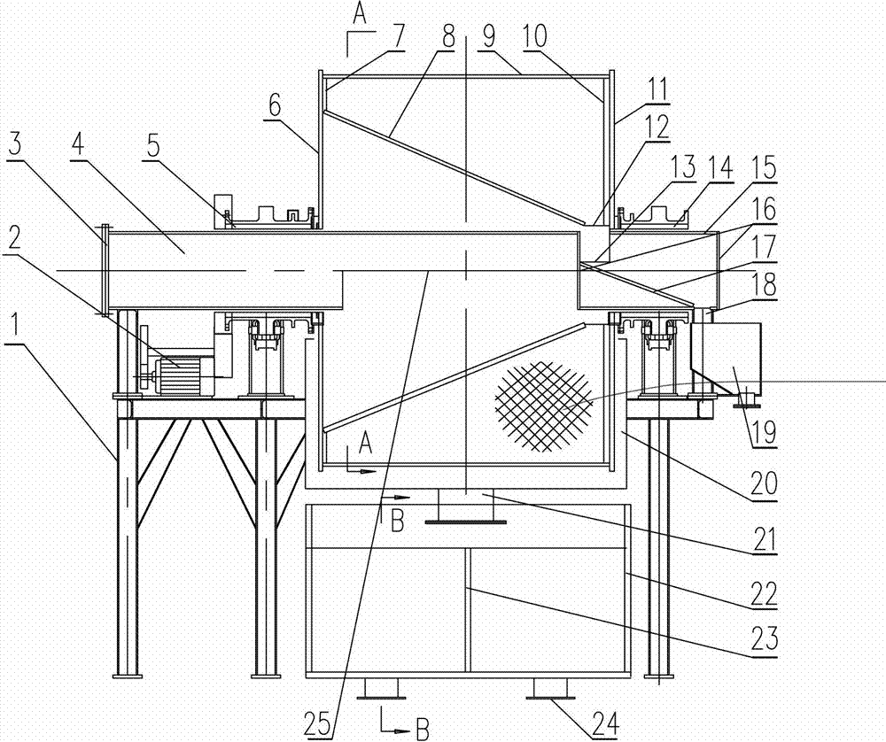
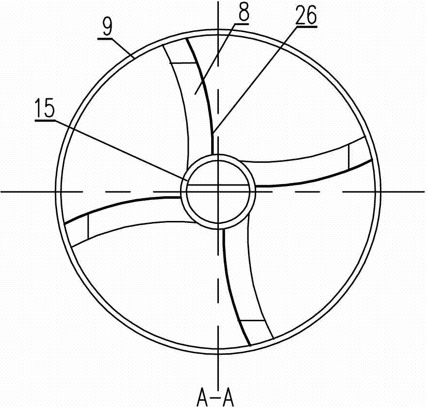
[0021] Such as figure 1 , 2 , 3, the cylindrical slag removal screen capable of distributing ore pulp of the present invention includes a frame 1, a fixed feeding pipe arranged on the frame 1, a cylindrical screen connected in rotation with the frame 1, and the The driving device 2 connected to the cylindrical sieve. The cylindrical sieve is composed of a cylindrical cylinder 9 with screen holes on the surface, a left end plate 6 and a right end plate 11 welded to the two ends of the cylindrical cylinder 9 respectively, and the left end plate 11 and the left end plate respectively. The plate 6, the right end plate 11 are fixedly connected to the driving hollow shaft 5 and the driven hollow shaft 14. The driving hollow shaft 5 is connected to the driving device 2, and the characteristic is that the inner space of the cylindrical sc...


PUM


Abstract

The invention belongs to the technical field of slag removing equipment of beneficiation plants, and particularly relates to a slag removing drum screen capable of distributing pulp. The slag removing drum screen comprises a frame, a fixed feed tube, a drum screen body and a driving device, wherein the drum screen body consists of a cylinder, a left end plate, a right end plate, a hollow driving shaft and a hollow driven shaft, the hollow driving shaft is connected with the driving device, a group of filtering and slag discharging boxes are obliquely arranged in an inner space of the drum screen body, a pulp receiving box is arranged on the outer periphery of the lower half portion of the drum screen body, a pulp distribution box is arranged below the pulp receiving box, a central feed hole is arranged on the left end plate of the drum screen body, a central slag hole is arranged on the right end plate, one end of the fixed feed tube is connected with a feed connector, the other end of the fixed feed tube penetrates through the central feed hole to be connected with a slag discharge tube, and a slag receiving hopper is arranged below the slag discharge tube. The slag removing drum screen capable of distributing the pulp is reasonable in arrangement, simple to mount, convenient to use, less in maintenance and capable of distributing the pulp, removing slag in the pulp and protecting operation equipment at the lower segment, and production can be guaranteed to be smooth beneficially.

Description

technical field [0001] The invention belongs to the technical field of slag removal equipment in mineral processing plants, in particular to a cylindrical slag removal screen capable of distributing ore pulp. Background technique [0002] During the mining process, due to the need for blasting, explosive debris, tree roots, turf and many other debris are mixed into the ore. These sundries will eventually enter the beneficiation process. Some sundries will be ground in the process of crushing and grinding, which has little effect on production; but some sundries have great toughness. It is difficult to be ground, and finally forms slag, which has a very bad influence on the subsequent process of beneficiation. Iron ore concentrators mainly use magnetic separation for separation, and these debris will cause blockage when entering the magnetic separation, especially for flat ring strong magnetic machines and vertical ring strong magnetic machines. , reducing the operating ra...

Claims


Application Information

Patent Timeline
Patent Type & Authority Applications(China)
IPC IPC(8): B07B1/22
Inventor 李国洲包士雷罗远秋
Owner MCC NORTH (DALIAN) ENG TECH CO LTD
Why Eureka
Try Eureka