LTCC (Low Temperature Co-Fired Ceramic) broadband power divider

A power divider and broadband technology, applied in the field of low temperature co-fired ceramic power divider and power divider, can solve the problems of not meeting the miniaturization requirements of radio frequency circuits and occupying a large area, so as to facilitate mass production and manufacturing The effect of low cost and high isolation

Inactive Publication Date: 2013-01-02
SUZHOU R&D CENT OF NO 214 RES INST OF CHINA NORTH IND GRP
View PDF5 Cites 25 Cited by
  • Summary
  • Abstract
  • Description
  • Claims
  • Application Information

AI Technical Summary

Problems solved by technology

[0003] The traditional power divider generally adopts the form of Wilkinson power divider, and realizes impedance matching through a quarter-wavelength impedance line. The impl

Method used


Image

  • LTCC (Low Temperature Co-Fired Ceramic) broadband power divider
  • LTCC (Low Temperature Co-Fired Ceramic) broadband power divider
  • LTCC (Low Temperature Co-Fired Ceramic) broadband power divider

Examples


Embodiment Construction

[0033] The present invention will be described in detail below in conjunction with the accompanying drawings and specific embodiments.

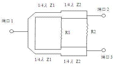
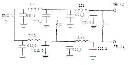
[0034] figure 1 It is the prototype circuit diagram of two-stage Wilkinson broadband power splitter. In the figure, the lengths of the two impedance converters are transmission lines with a quarter wavelength λ, and the characteristic impedances of the transmission lines are Z1 and Z2 respectively. figure 2 is equivalent to a reactance network with lumped parameters figure 1 Two quarter-wavelength transmission lines in . The purpose of the present invention is exactly to realize in as little as possible volume range with LTCC technology figure 2 All capacitors C11_1, C11_2, C12_1, C12_2, C21_1, C21_2, C22_1, C22_2, inductors L11, L12, L21, L22 and resistors R1, R2 in the components.

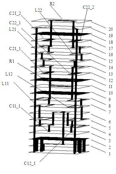
[0035] image 3 shown is implemented using LTCC figure 2 3D structure diagram of all lumped parameter elements in . There are 20 dielectric layers in ...


PUM


Abstract

The invention discloses a broadband LTCC (Low Temperature Co-Fired Ceramic) power divider which is formed by connecting two stages of impedance transformers in series. Each stage of impedance transformer is formed by a reactance network formed by elements with lumped parameters; and the elements are implemented by a LTCC multilayer structure. The two stages of impedance transformers adopt a vertical series connection structure. The elements of the first stage of impedance transformer are positioned on a second layer to a ninth layer of a LTCC medium; and the elements of the second stage of impedance transformer are positioned on an eleventh layer to an eighteenth layer of the LTCC medium. An isolation resistance at the tail end of the first stage of impedance transformer is positioned on a tenth layer of the LTCC medium and is implemented by printing resistance paste; and an isolation resistance at the tail end of the second stage of impedance transformer is positioned on a nineteenth layer of the LTCC medium and is implemented by printing the resistance paste. The two stages of impedance transformers are isolated by metal grounds on the ninth layer and the eleventh layer in phase mode. The power divider has the advantages of small volume, low cost, wide bandwidth, high isolation, high temperature stability, convenience in use and the like and is beneficial to batch production.

Description

technical field [0001] The invention belongs to the field of electronic technology, and relates to a power divider, in particular to a low-temperature co-fired ceramic (LTCC) power divider considering the packaging structure. Background technique [0002] The power splitter is an important three-port passive device in the radio frequency circuit. Its main function is to realize the equal power and equal phase distribution of the input signal, or on the contrary to realize the equal power and equal phase combination of two input signals. A good power splitter requires a relatively wide operating frequency band, low insertion loss, good amplitude and phase consistency of the two signals, and high isolation between the two signals. In addition, the smallest possible size of the power divider is also a requirement for the development of electronic systems towards miniaturization and light weight. [0003] The traditional power divider generally adopts the form of Wilkinson powe...

Claims


Application Information

Patent Timeline
IPC IPC(8): H01P5/16
Inventor 汪杰黄勇张慧景王啸薛峻
Owner SUZHOU R&D CENT OF NO 214 RES INST OF CHINA NORTH IND GRP
Why Eureka
Try Eureka