Microwave optical fiber link device for long-distance transmission of radar reference frequency signals

A reference frequency signal and optical fiber link technology, which is applied in the field of radar detection, can solve the problems of elevation measurement error, large transmission insertion loss, large volume and weight, etc., and achieve the effects of reducing interference noise, small size, and reduced loss

Active Publication Date: 2013-01-02
INST OF ELECTRONICS CHINESE ACAD OF SCI
View PDF3 Cites 35 Cited by
  • Summary
  • Abstract
  • Description
  • Claims
  • Application Information

AI Technical Summary

Problems solved by technology

The radar system requires a stable phase (or the transmission delay of the corresponding frequency) for the transmission of the reference frequency signal. However, the phase of the traditional microwave feeder, such as the coaxial cable, is greatly affected by the external environment. In the temperature range of -50℃~-10℃, using a 100m coaxial cable to transmit X-band 9.6GHz will ...

Method used


Image

  • Microwave optical fiber link device for long-distance transmission of radar reference frequency signals
  • Microwave optical fiber link device for long-distance transmission of radar reference frequency signals
  • Microwave optical fiber link device for long-distance transmission of radar reference frequency signals

Examples


Embodiment Construction

[0023] The present invention will be described in detail below in conjunction with the accompanying drawings. It should be noted that the described implementations are considered for illustrative purposes only and not as limitations of the invention.

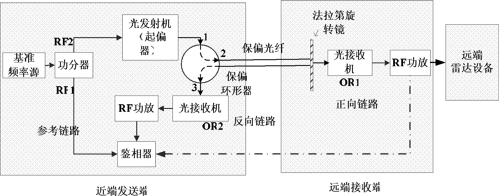
[0024] According to the present invention, figure 1 Shown is the system block diagram of the microwave fiber optic link device for long-distance transmission of radar reference frequency signals of the present invention. The figure includes four parts: near-end sending end, optical fiber, far-end sending end, and far-end radar equipment.

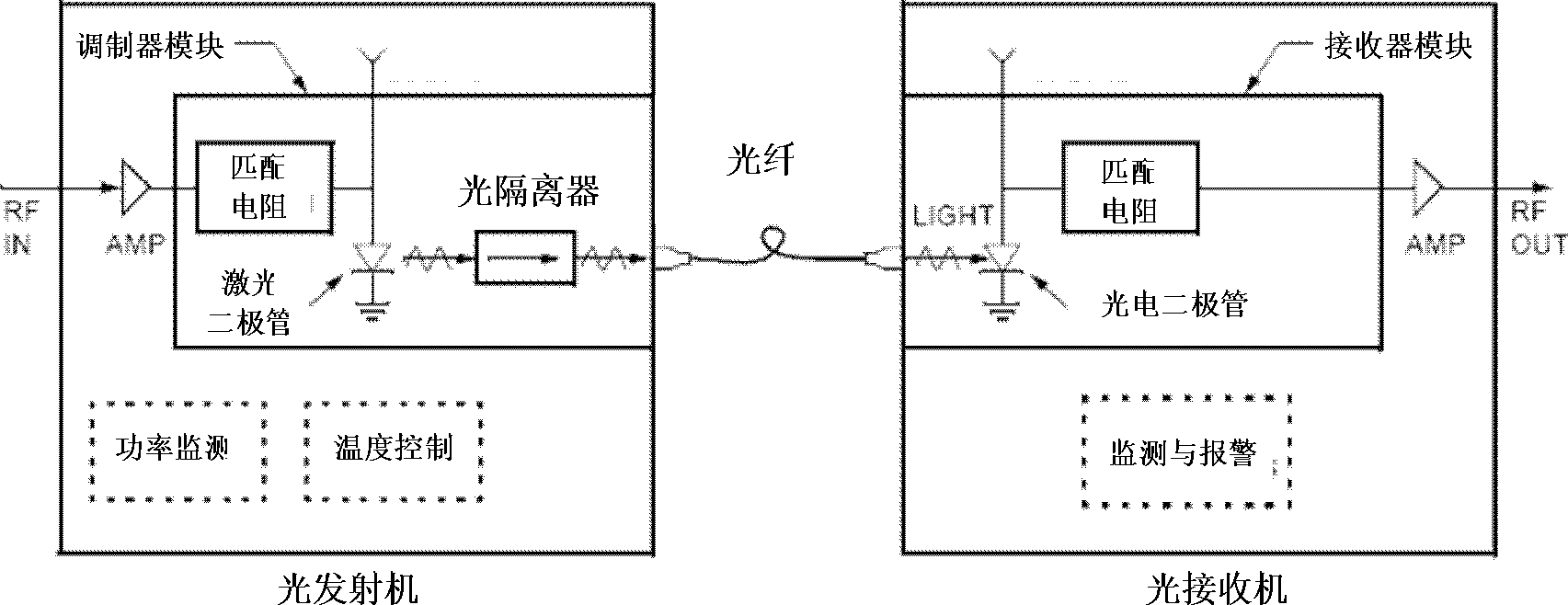
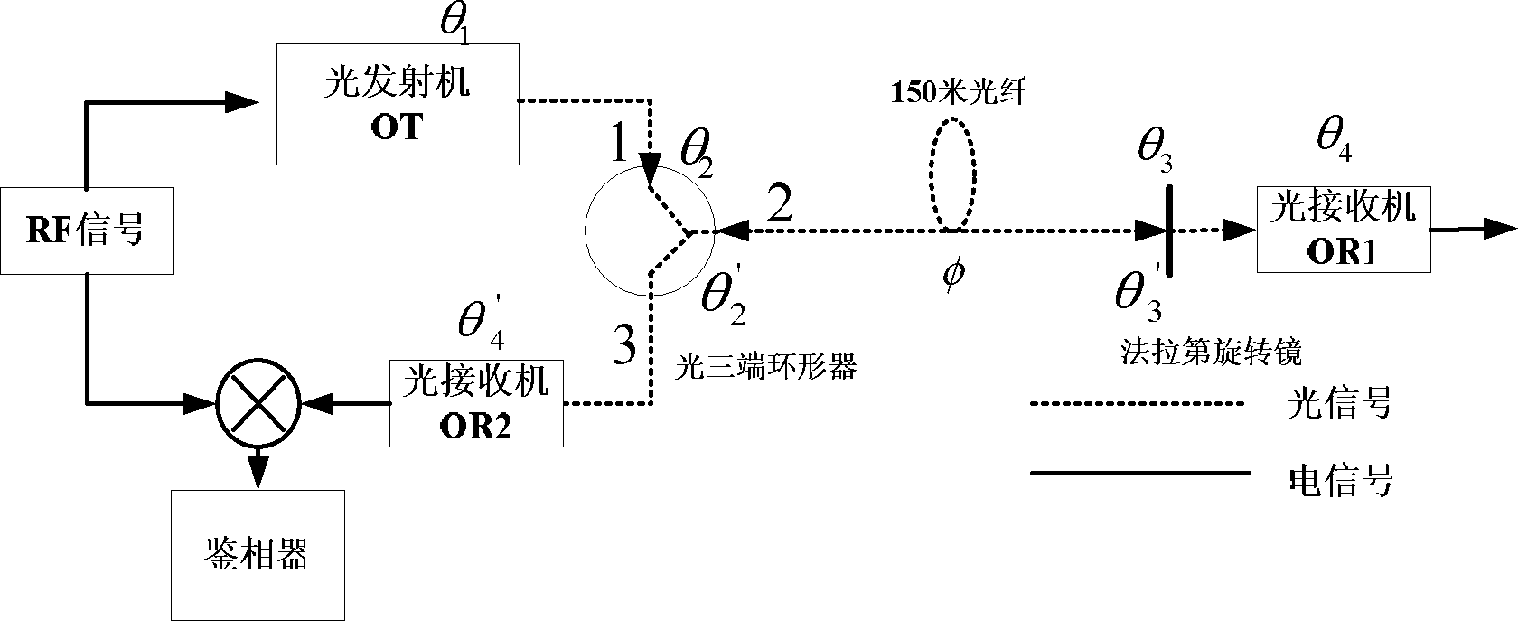
[0025] The near-end sending end is composed of a reference frequency source, a power divider, an optical transmitter, a polarization maintaining optical circulator, a radio frequency (RF) power amplifier, an optical receiver OR2, and a phase detector; the optical fiber is a 150m polarization maintaining optical fiber, thereby reducing the optical signal Interference noise that may be introduc...


PUM


Abstract

The invention discloses a microwave optical fiber link device for long-distance transmission of radar reference frequency signals and relates to the technology of radar detection. The microwave optical fiber link device consists of an optical emitter, an optical receiver, a Faraday rotating mirror, an optical circulator, a polarization maintaining optical fiber, a radio-frequency power amplifier and the like. By subjecting microwaves to electric-optical and optical-electric conversion and utilizing the advantages of low insertion loss and high-temperature phase stability of the optical fiber, the microwaves are transmitted in low phase fluctuation and loss in the long distance. The microwave optical fiber link device can be used for transmission of rate-aided signals of spatial long-base line interference synthetic aperture radar (SAR) and transmission of reference frequency signals of radar systems such as phased array radars and multi-base radar monitoring net. Besides, phase changes caused by environmental factors such as temperature and irradiation can be accurately compensated during long-distance transmission of X-wave band microwave signals, and meanwhile, the microwave optical fiber link device has ultrawide radio-frequency (RF) working band and can be developed for transmission of radar reference frequency signals ranging from 50MHz to18GHz.

Description

technical field [0001] The invention relates to the technical field of radar detection, and is a microwave optical fiber link device for long-distance transmission of radar reference frequency signals. Background technique [0002] In radar systems, long-distance stable transmission of microwave signals with reference frequency signals is usually required, such as calibration signal transmission in space long baseline dual-antenna interferometric SAR topographic mapping system, and reference frequency of radar systems such as phased array radar and multistatic radar monitoring network Signal transmission. The radar system requires a stable phase (or the transmission delay of the corresponding frequency) for the transmission of the reference frequency signal. However, the phase of the traditional microwave feeder, such as the coaxial cable, is greatly affected by the external environment. In the temperature range of -50℃~-10℃, using a 100m coaxial cable to transmit X-band 9....

Claims


Application Information

Patent Timeline
IPC IPC(8): H04B10/25G01S7/02
Inventor 王宇吴淑梅周良将郭磐梁兴东
Owner INST OF ELECTRONICS CHINESE ACAD OF SCI
Why Eureka
Try Eureka