High-power-factor direct-current current output light-emitting diode (LED) driving circuit with low-energy-storage capacitor

A high power factor, LED-driven technology, applied in the electronic field, can solve problems such as shortened life of electrolytic capacitors, and achieve the effect of improving life and high input power factor

Active Publication Date: 2013-01-02
邳州市景鹏创业投资有限公司
View PDF4 Cites 8 Cited by
  • Summary
  • Abstract
  • Description
  • Claims
  • Application Information

AI Technical Summary

Problems solved by technology

For every ten degrees increase in ambient temperature, the life of electrolytic capacitors is doubled

Method used


Image

  • High-power-factor direct-current current output light-emitting diode (LED) driving circuit with low-energy-storage capacitor
  • High-power-factor direct-current current output light-emitting diode (LED) driving circuit with low-energy-storage capacitor
  • High-power-factor direct-current current output light-emitting diode (LED) driving circuit with low-energy-storage capacitor

Examples


Embodiment 1

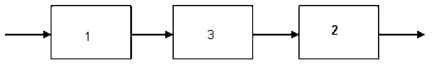
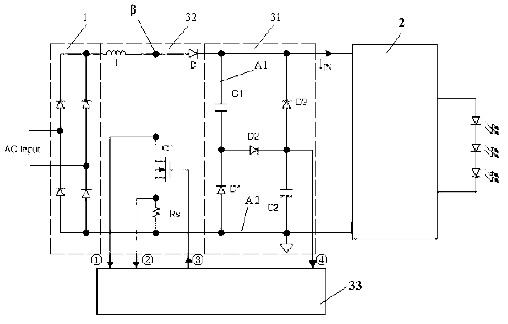
[0061] Embodiment 1, a kind of LED driving circuit of low energy storage capacitance, high power factor direct current output, such as figure 2 Shown: includes a diode rectifier bridge 1, an active nonlinear capacitor network 3 and a subsequent switching power converter 2.

[0062] 1. The diode rectifier bridge 1 is composed of 4 diodes (conventional technology).

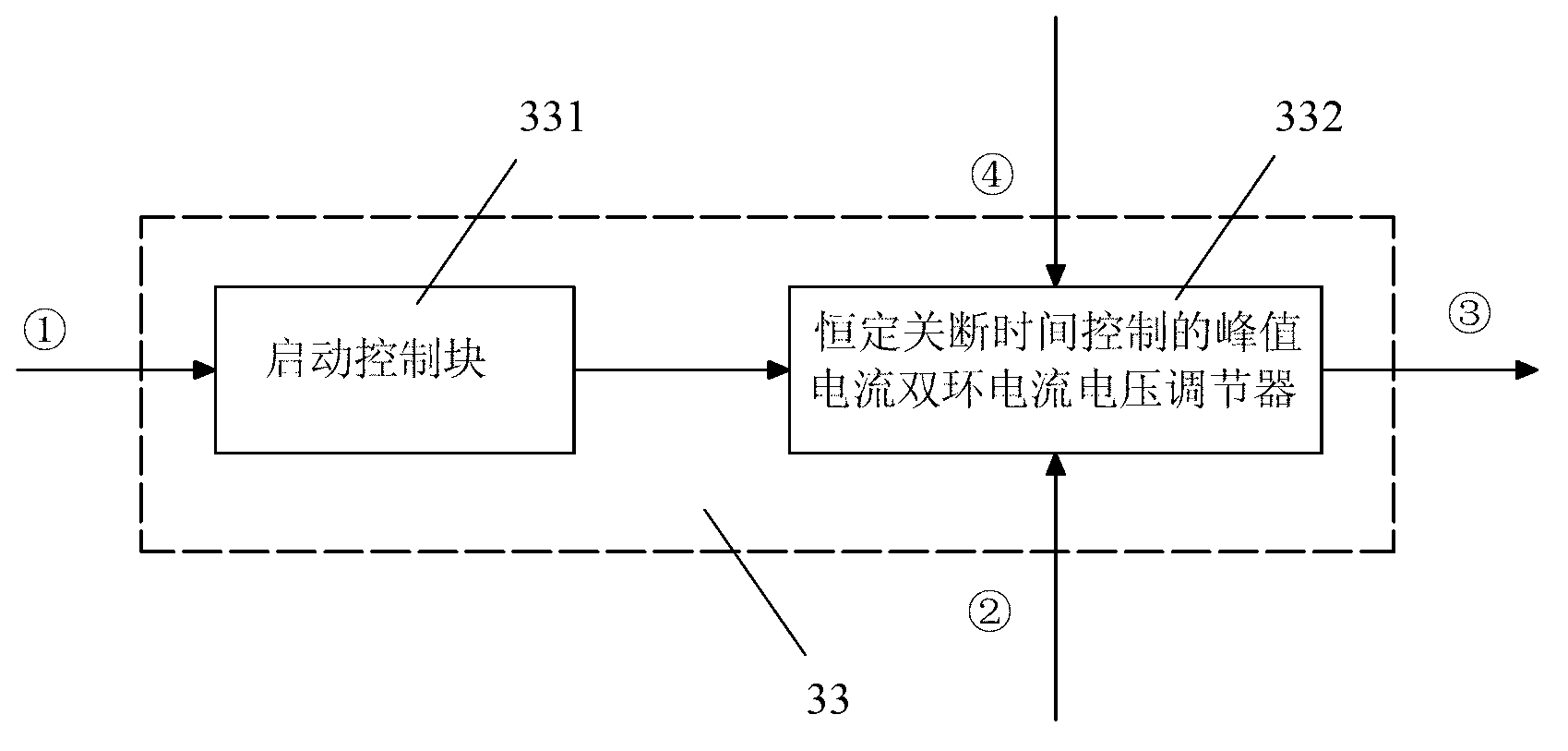
[0063] 2. The active nonlinear capacitor network is specifically composed of a valley filling circuit 31 , a Boost circuit 32 and a module 33 .

[0064] 1) The valley filling circuit 31 is composed of capacitors C1, C2 and diodes D1, D2 and D3.

[0065] Defined as follows:

[0066] The connection A1 between the capacitor C1 and the diode D3 is the positive terminal of the valley filling circuit 31 .

[0067] The connection A2 between the capacitor C2 and the diode D1 is the negative terminal (ie, the ground terminal) of the valley filling circuit 31 .

[0068] The capacitor C1 and the diode D1 form a branch, in...

Embodiment 2

[0090] exist figure 2 Add a diode Din on the basis of Figure 7 shown.

[0091] details as follows:

[0092] like Figure 7 Shown: in figure 2 On the basis of above, a diode Din is added, the anode of the diode Din is connected to the output positive terminal of the diode rectifier bridge 1 , and the cathode of the diode Din is connected to the positive terminal of the valley filling circuit 31 . because Figure 7 Among them, the output end of the diode rectifier bridge 1 has two branches to supply power to the valley filling circuit 31, one is to directly supply power to the valley filling circuit 31 through the diode Din; the other is to supply power to the valley filling circuit 31 through the inductor L, the power switch Q1, and the current detection resistor R S and the diode D form an active boost circuit (ie, Boost boost circuit 32 ) to supply power to the valley filling circuit 31 .

[0093] The corresponding control interval of the LED driving circuit describe...


PUM


Abstract

The invention discloses a high-power-factor direct-current current output light-emitting diode (LED) driving circuit with a low-energy-storage capacitor. The LED driving circuit is composed of a diode rectifying bridge (1), an active non-linear capacitor network (3) and a follow-up switch power converter (2). The output end of the diode rectifying bridge (1) supplies power to the active non-linear capacitor network (3). Output voltage of the active non-linear capacitor network (3) is formed by overlapping direct current voltage with alternating current voltage with twice of electric supply frequency. The output voltage of the active non-linear capacitor network (3) supplies power to the follow-up switch power converter (2). The active non-linear capacitor network (3) is composed of a lower-energy-storage capacitor and an active switch network. By means of the LED driving circuit, the low-capacitance capacitor (such as a thin film capacitor and a ceramic medium capacitor) can be utilized to finish the energy storage function.

Description

technical field [0001] The invention belongs to the field of electronic technology, and relates to AC and DC current conversion and power control. More specifically, the present invention relates to an LED driving circuit with low energy storage capacitance and high power factor direct current output for LED lighting. Background technique [0002] The LED integrated lamp is composed of three parts: the LED module, the heat sink and the LED drive power supply; the heat sink is responsible for the thermal power P generated by the LED module H transferred to the ambient air; the thermal power P transferred by the heat sink H It is determined by the thermal resistance RS of the radiator and the temperature difference ΔT between the radiator and the ambient air: P H =ΔT / R S . Heat sink thermal resistance R S It is determined by the surface area SS of the heat sink (the volume of the heat sink): R S =K / SS. The temperature difference ΔT between the radiator and the ambient ...

Claims


Application Information

Patent Timeline
Patent Type & Authority Applications(China)
IPC IPC(8): H05B37/02
Inventor 翁大丰魏其萃
Owner 邳州市景鹏创业投资有限公司
Why Eureka
Try Eureka