Line scanning confocal imaging image guidance-based self-adaption confocal scanning retina imaging method and device

A confocal scanning and image-guided technology, applied in applications, eye testing equipment, medical science, etc., can solve the problems of poor imaging resolution, small imaging field of view, and impossibility of large-field imaging, achieving accurate and reliable positioning, The effect of high-resolution imaging

Active Publication Date: 2013-01-09
INST OF OPTICS & ELECTRONICS - CHINESE ACAD OF SCI
View PDF5 Cites 12 Cited by
  • Summary
  • Abstract
  • Description
  • Claims
  • Application Information

AI Technical Summary

Problems solved by technology

This adaptive confocal scanning imaging technology has good imaging effects, but it still has its own defects: due to the point scanning method, the imaging field of view is small, only 1-3 degrees, corresponding to the retinal plane is about 290-870 microns, Although other retinal regions near the central area of ​​the visual axis can be observed through the guidance of the other eye optotype system, the imaging range is limited to about 8 degrees due to the layout area of ​​the optotype dot matrix, and an imaging field of about 30 degrees is usually required for retinal pathological observation. Field range, corresponding to the retinal plane is about 9.5mm, this system cannot achieve this function
This line-scanning confocal system uses one-dimensional line scanning to image the fundus retina. Compared with laser confocal ophthalmoscopes that use point scanning, the imaging field of view is larger, which is convenient for observing the retina in a wide range. However, due to the large field of view imaging The resolution of the retina is poor, and it needs to be combined with high-resolution small field of view imaging to observe the fine structure of the retina

Method used


Image

  • Line scanning confocal imaging image guidance-based self-adaption confocal scanning retina imaging method and device
  • Line scanning confocal imaging image guidance-based self-adaption confocal scanning retina imaging method and device
  • Line scanning confocal imaging image guidance-based self-adaption confocal scanning retina imaging method and device

Examples


Embodiment Construction

[0044] The present invention will be further described below in conjunction with the accompanying drawings and specific embodiments.

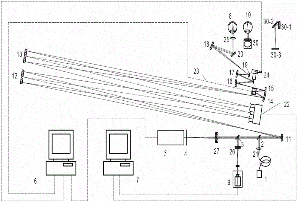
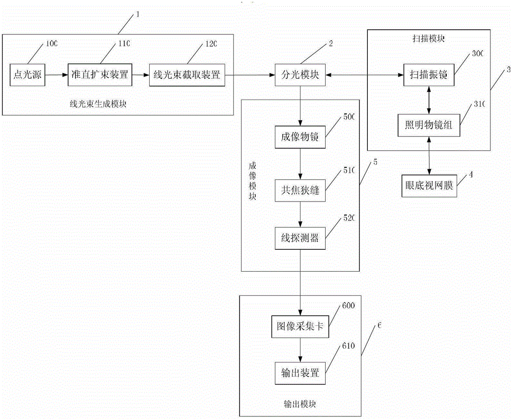
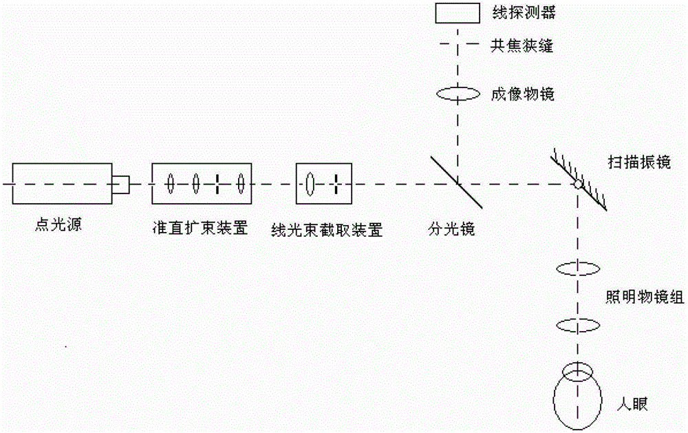
[0045] Such as Figure 6 As shown, it is a structural diagram of the adaptive confocal scanning retinal imaging system based on the line scanning confocal imaging image guidance of the present invention, and the adaptive confocal scanning retinal imaging system and method based on the line scanning confocal imaging image guidance of the present invention , including a line-scanning confocal imaging unit 101 , a spectroscopic unit 102 , an adaptive confocal scanning retinal imaging unit 103 , a processor 104 and a display 105 .

[0046] The line-scan confocal imaging unit 101 is connected to the spectroscopic unit 102 and the processor 104. The line-scan confocal imaging unit 101 includes a line beam generating module, a spectroscopic module, a scanning module, an imaging module and an output module. The line-scan confocal imaging unit 101 is a...


PUM


Abstract

The invention relates to a line scanning confocal imaging image guidance-based self-adaption confocal scanning retina imaging method and device. By adopting the method, on the basis that one-dimensional scanning is performed on fundus retinae by a line scanning confocal imaging unit to obtain large-visual field imaging of the retinae, local small region positions of the retinae can be randomly selected and are marked from large-visual field imaged images, and a self-adaption confocal scanning retina imaging unit can be used for realizing accurate positioning on the small regions of the retinae and performing high-resolution imaging on the small regions. According to the line scanning confocal imaging image guidance-based self-adaption confocal scanning retina imaging method and device, the large-visual field imaging of the line scanning confocal fundus retinae and the accurate high-resolution imaging of the small region positions of the self-adaption confocal scanning fundus retinae can be obtained at the same time. Under the image guidance of the fundus retinae large-visual field imaging acquired by the line scanning confocal imaging unit, the accurate positioning can be realized on the local small regions by the self-adaption confocal scanning retinae imaging unit, and meanwhile, the high-resolution imaging is realized on the small region positions.

Description

technical field [0001] The invention relates to the field of bio-ophthalmology imaging, in particular to an adaptive confocal scanning retinal imaging method and device based on line-scanning confocal imaging image guidance. Background technique [0002] At present, there are three main technologies for retinal imaging in vivo: fundus camera, optical coherence tomography and laser confocal scanning ophthalmoscope, all of which have been successfully applied. In order to ensure the brightness of the illumination, the fundus camera uses a traditional thermal light source as the lighting device of the system, so its resolution is low, usually at the level of tens of microns, and it cannot effectively observe the fine structure of the retina at the micron level. In particular, the longitudinal resolution of the fundus camera The rate is lower, and the layered tissue inside the retina cannot be observed. Optical coherence tomography technology is essentially a low-coherence inte...

Claims


Application Information

Patent Timeline
Patent Type & Authority Applications(China)
IPC IPC(8): A61B3/12A61B3/14
Inventor 张雨东何益史国华
Owner INST OF OPTICS & ELECTRONICS - CHINESE ACAD OF SCI
Why Eureka
Try Eureka