Discharge-induced explosion loading driving device

A technology of driving device and electric explosion, which is applied in the direction of measuring device, impact test, machine/structural component test, etc., can solve the problems such as difficulty in cutting flying pieces of plexiglass barrel, ablation of metal projectiles, etc., to overcome flying pieces The effect of difficult cutting, complete structure and small time drift

Inactive Publication Date: 2013-01-09
INST OF FLUID PHYSICS CHINA ACAD OF ENG PHYSICS
View PDF4 Cites 3 Cited by
  • Summary
  • Abstract
  • Description
  • Claims
  • Application Information

AI Technical Summary

Problems solved by technology

However, if relying on the method of increasing the thickness of the plastic sheet, there will be the problem of difficulty in cutting the flying pieces with the plexiglass barrel; if the plastic sheet is directly replaced with a metal projectile with a higher density, there will be high-voltage discharges that will cause partial damage to the metal projectile. ablation problem

Method used


Image

  • Discharge-induced explosion loading driving device
  • Discharge-induced explosion loading driving device
  • Discharge-induced explosion loading driving device

Examples


Embodiment Construction

[0012] The present invention will be further described below in conjunction with the accompanying drawings and embodiments.

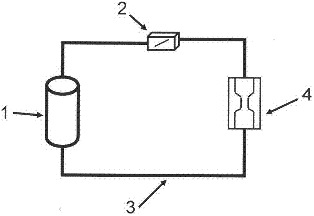
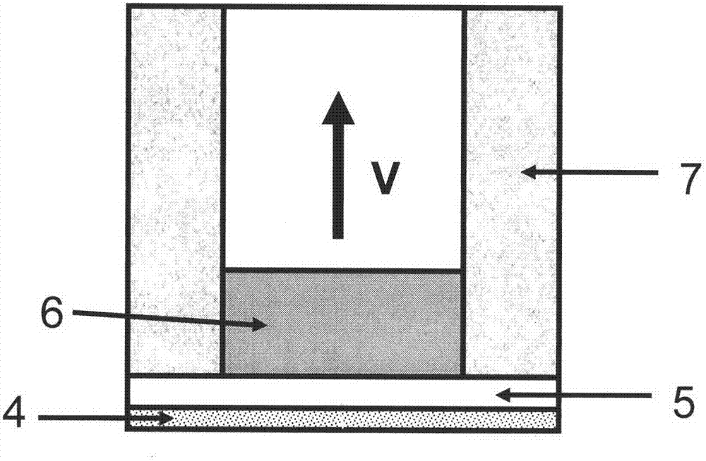
[0013] like figure 1 and figure 2 , an electric explosion loading driving device, comprising a barrel 7, an insulating sheet 5 that is close to the bottom of the barrel 7, a metal bridge foil 4 that is close to the lower surface of the insulating sheet 5, and the two ends of the metal bridge foil 4 are connected with electric transmission lines 3. It is characterized in that: the barrel 7 is equipped with a high-density projectile 6 , and the high-density projectile 6 is bonded to the upper surface of the insulating sheet 5 . in:

[0014] figure 1 It is the system layout diagram of the present invention. The present invention uses the energy stored in the capacitor 1, which is generally tens of kilojoules, to discharge through a series circuit, and to drive the metal projectile 6 through the electric explosion of the metal bridge foil 4, so as to co...


PUM


Abstract

The invention discloses a discharge-induced explosion loading driving device, which comprises a gun barrel (7), an insulating flake (5) closely clinging to the bottom of the gun barrel (7) and a metal bridge foil (4) closely clinging to the lower surface of the insulating flake (5). Transmission lines (3) are connected to the two ends of the metal bridge foil (4). The device is characterized in that a high-density projectile body (6) is arranged in the gun barrel (7), and is adhered to the upper surface of the insulating flake (5). The characteristics of easiness for operation, low time drift and the like of discharge-induced explosion loading are kept, and the device also has the advantages of structural integrity of a loaded high-density projectile body, stable flight state without rotation, speed stability and controllability within a medium/low-speed range, and the like, and is applied to a miniature crash test with high requirements on time synchronization and low requirements on speed.

Description

technical field [0001] The invention belongs to the technical field of dynamic loading, and in particular relates to an electric explosion loading driving device for a metal bridge foil electric explosion driving projectile. Background technique [0002] The flyer electric explosion loading technology (electric gun) invented in the 1960s has been widely used in various shock wave physics and detonation physics experiments. The flyer electric explosion loading device consists of two parts: an energy system and a bridge foil-flyer assembly. The energy system includes an energy storage capacitor, a charging circuit, a main discharge circuit and its control system, and its main function is to provide the metal bridge foil with the energy required for its electric explosion. The bridge foil-flyer assembly includes metal bridge foil, plastic sheet and plexiglass barrel. Its main function is to generate high-temperature and high-pressure metal gas by electric explosion, and push t...

Claims


Application Information

Patent Timeline
Patent Type & Authority Applications(China)
IPC IPC(8): G01M7/08
Inventor 李涛傅华李强唐孝容龚晏青
Owner INST OF FLUID PHYSICS CHINA ACAD OF ENG PHYSICS
Why Eureka
Try Eureka