
Submersible motor for well

A technology for submersible motors and shafts, which is applied in the field of submersible motors for wells and submersible electric pumps. It can solve the problems of limited pressure difference between the inside and outside of the motor, the entry of impurities, and the increase in deformation resistance, so as to avoid excessive internal and external pressure differences and rotation of the shaft. Smooth, increased cooling effect

Active Publication Date: 2013-01-09
浙江东音科技有限公司
View PDF14 Cites 8 Cited by
  • Summary
  • Abstract
  • Description
  • Claims
  • Application Information

AI Technical Summary

Problems solved by technology

Although the above two types of motors can achieve pressure balance in the inner cavity of the motor, due to the very limited expansion and contraction capacity of the oil bladder or rubber bladder; that is to say, the difference between the internal and external pressure of the adjustment motor is limited.
If the thickness of the oil bladder or rubber bladder is enhanced, the deformation resistance will increase and the deformation will be affected.
When the motor dives too deep, the oil bag or rubber bag will break, and impurities will enter the motor with the water, which will cause damage to the motor
To sum up, the current solution cannot solve the adverse effects caused by the excessive pressure difference between the inside and outside of the motor.

Method used


Image

  • Submersible motor for well
  • Submersible motor for well
  • Submersible motor for well

Examples


Embodiment Construction

[0028] The following are specific embodiments of the present invention and in conjunction with the accompanying drawings, the technical solutions of the present invention are further described, but the present invention is not limited to these embodiments.

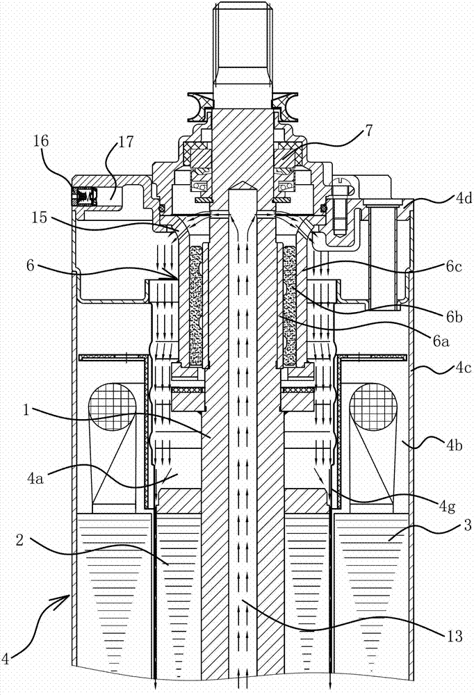
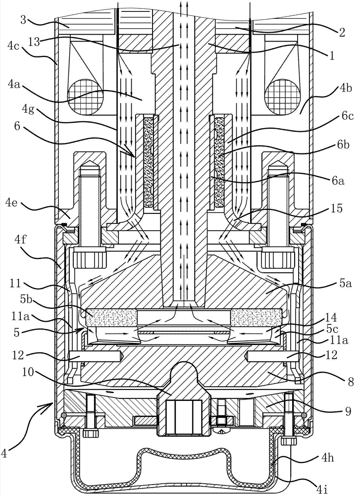
[0029] Such as figure 1 with figure 2 As shown, the submersible motor for this well includes a shaft 1, a rotor 2, a stator 3, and a housing assembly 4 with an inner cavity 4a and an outer cavity 4b.

[0030] The casing assembly 4 includes components such as a barrel 4c, an upper fixing seat 4d, a lower fixing seat 4e, a lower supporting seat 4f, a shielding sleeve 4g, a water bag 4h, and a base 4i.

[0031] The upper fixing seat 4d is fixed and sealingly connected with the upper end of the barrel 4c, and the lower fixing seat 4e is fixed and sealingly connected with the lower end of the barrel 4c. The shielding sleeve 4g is located in the machine barrel 4c, and the upper and lower ends of the shielding sleeve 4g are re...


PUM


Abstract

The invention provides a submersible motor for a well and belongs to the technical field of mechanical engineering. The submersible motor solves the problem that the existing submersible motor for the well is poor in rotation stability of a rotation shaft and short in service life. The submersible motor for the well comprises the rotation shaft, a rotor, a stator and a casing assembly with an inner cavity and an outer cavity, the rotation shaft is located in the inner cavity, the upper end of the rotation shaft penetrates out of the casing assembly, and the upper end portion and the lower end portion of the rotation shaft are respectively in location connection with the casing assembly through a ceramic graphite radial load bearing assembly. The submersible motor for the well adopts measures of adopting ceramic graphite bearings, adding cooling effects in water circulation in the inner cavity, arranging a check valve to avoid big inside and outside differential pressure and the like, so that the submersible motor has the advantages of being stable in rotation of the rotation shaft, stable in performance and long in service life.

Description

technical field [0001] The invention belongs to the technical field of mechanical engineering and relates to a submersible electric pump, in particular to a submersible motor for wells. Background technique [0002] A submersible pump is a type of water pump in which both the impeller of the pump body and the motor driving the impeller are submerged in water. The motors used in submersible pumps are dry (the motor is completely sealed), semi-dry (the stator of the motor is sealed, and the rotor runs in water), oil-filled (the inside of the motor is filled with oil to prevent moisture from entering the windings) and wet (the inside of the motor is sealed). water-filled, both the stator and the rotor operate in water) and other types. Documents about submersible electric pumps, such as a support device for a water-filled submersible electric pump motor shaft disclosed in Chinese patent literature [application number: 200820003903.5; announcement number: CN201159192Y], the sha...

Claims


Application Information

Patent Timeline
Patent Type & Authority Applications(China)
IPC IPC(8): H02K5/16H02K9/19
Inventor 方秀宝米勇吴刚
Owner 浙江东音科技有限公司
Learn More