Decompression mechanism of engine and engine

A decompression mechanism and engine technology, which is applied in the direction of engine components, machines/engines, mechanical equipment, etc., can solve the problems of increasing the load on the motor, high frequency of engine failure, and difficulty in starting the engine, so as to reduce the starting resistance , The effect of reducing the frequency of failure

Inactive Publication Date: 2013-01-16
四川银钢一通凸轮轴有限公司
View PDF7 Cites 3 Cited by
  • Summary
  • Abstract
  • Description
  • Claims
  • Application Information

AI Technical Summary

Problems solved by technology

[0005] The structure of the above-mentioned engine is simple and compact, but because the tappet 03 reciprocates in the guide hole, and the mass of the external parts in the engine is relatively large, the engine needs to overcome greater friction and inertia when starting
[0006] After increasin

Method used


Image

  • Decompression mechanism of engine and engine
  • Decompression mechanism of engine and engine
  • Decompression mechanism of engine and engine

Examples


Embodiment Construction

[0035] The embodiment of the present invention discloses a decompression mechanism of an engine to achieve the purpose of reducing the frequency of malfunctions during engine startup after the displacement of the engine is increased. The embodiment of the invention also discloses an engine.

[0036] The following will clearly and completely describe the technical solutions in the embodiments of the present invention with reference to the accompanying drawings in the embodiments of the present invention. Obviously, the described embodiments are only some, not all, embodiments of the present invention. Based on the embodiments of the present invention, all other embodiments obtained by persons of ordinary skill in the art without making creative efforts belong to the protection scope of the present invention.

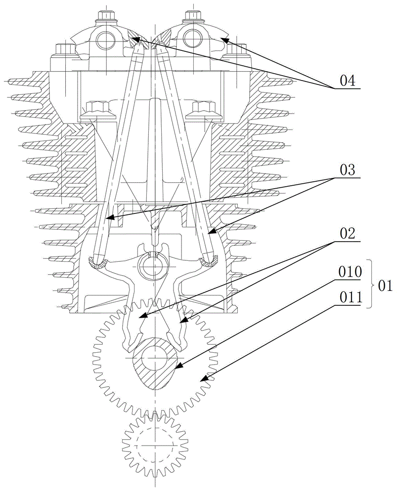
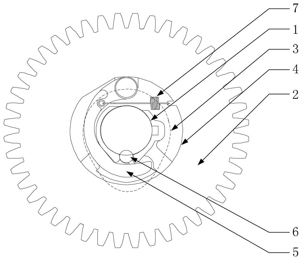
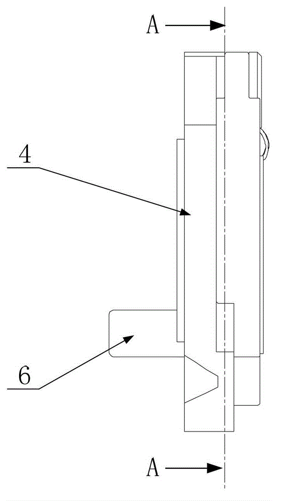
[0037] Please refer to Figure 2 to Figure 6 , The decompression mechanism of the engine provided by the present invention includes a central shaft 1, a gear 2, a camsha...


PUM


Abstract

The invention discloses a decompression mechanism of an engine. The decompression mechanism comprises a central shaft, a gear, a camshaft and a decompression disk, wherein the gear, the camshaft and the decompression disk are fixedly arranged on the central shaft. A rocking arm, a decompression pin and an elastic reset component are arranged on the decompression disk; the rocking arm is connected with the decompression disk through a hinge shaft; a first limiting part is arranged at one end of the rocking arm; the decompression pin is rotatablely arranged in a pressure relief hole; a second limiting part which can be stirred by the first limiting part is arranged at one end of the decompression pin; a first surface capable of forming a complete cambered surface with the surface of the camshaft and a second surface capable of protruding the surface of the camshaft are arranged at the other end of the decompression pin; and the elastic reset component stirs the decompression pin to the second surface to protrude the surface of the camshaft through the rocking arm. When the engine is started, the decompression pin protrudes the surface of the camshaft, is able to push a lower rocking arm to rotate, so as to open an exhaust valve to release the air pressure in a cylinder, and the purposes of decreasing starting resistance and reducing a frequency at which failures occur in the process that the engine is started are realized. The invention also provides the engine using the decompression mechanism.

Description

technical field [0001] The present invention relates to the technical field of engines, more specifically, to a decompression mechanism of an engine, and also to an engine. Background technique [0002] The camshaft layout of the engine is divided into two types: the overhead camshaft (OHC, Overhead Camshaft) and the bottom camshaft (OHV, Overhead Valve). Among them, the OHV engine does not need to set multi-valve, double camshaft or high-strength valves. Structures such as the cylinder head cover have the characteristics of small size and compact structure, and can output high torque at low speeds, and are more suitable for use in small motor vehicles such as motorcycles. [0003] figure 1 A bottom camshaft structure in a common engine is shown, including camshaft assembly 01, lower rocker arm 02, tappet 03, valve rocker arm 04 and other components. The camshaft assembly 01 includes the gear 010 and the cam 011; the lower rocker arm 02 is an L-shaped structure, the middle...

Claims


Application Information

Patent Timeline
IPC IPC(8): F01L13/08
Inventor 伍良前曾大晋肖冬任剑明
Owner 四川银钢一通凸轮轴有限公司
Why Eureka
Try Eureka