Hydrostatic drive system

A hydrostatic drive and hydraulic technology, applied in the field of hydrostatic drive system, can solve the problems of complex structure, structure consumption, etc.

Inactive Publication Date: 2013-01-16
LINDE HYDRAULICS
View PDF6 Cites 9 Cited by
  • Summary
  • Abstract
  • Description
  • Claims
  • Application Information

AI Technical Summary

Problems solved by technology

The direct loading of the regulating device by the hydraulic return signal generated on the circulating pressure balance is due to the required pressure medium volume (in order to generate the required regulating force on the regulating piston device by the hydraulic return signal to make the delivery of the pump The volume flow adjustment mechanism swings ...

Method used


Image

  • Hydrostatic drive system
  • Hydrostatic drive system

Examples


Embodiment Construction

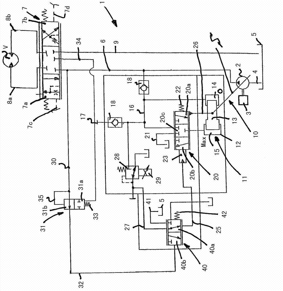
[0029] exist figure 1 A circuit diagram of a load-sensing regulated drive system 1 according to the present invention is shown in . The drive system 1 is used, for example, in mobile work machines, preferably excavators or ground vehicles.

[0030] The drive system 1 has a pump 2 with an adjustable delivery volume flow, which is operated in an open circuit and is in drive connection with a drive machine 3 , for example an internal combustion engine, for drive. The pump 2 is connected on the suction side to a container 5 by means of a line 4 and delivers pressure medium into a delivery line 6 .

[0031] In order to control one or more consumers V, a control valve 7 is provided in each case, which is designed as a directional valve that throttles in the middle position.

[0032] The control valves 7 are connected to the delivery line 6 , a container line 9 and pressure medium lines 8 a , 8 b leading to consumers V in each case. When the control valve 7 is actuated, the contro...


PUM


Abstract

The invention relates to a hydrostatic drive system, having a conveying volume flow adjustable pump, wherein the pump is set to supply for at least one consumption unit; a conveying volume flow adjusting device for the pump controls toward the direction of increasing the conveying volume flow by means of the preset signal and controls towards the direction of reducing the conveying volume flow according to the hydraulic reset signal of the volume flow which is conveyed excessively; a circulating pressure balance is set to generate a reset signal at the reset signal generating position; a pressure adjusting valve is set to control the conveying volume flow adjusting device of the pump, and can be loaded by a preset signal. The pressure adjusting valve is made as a pre-control pressure adjusting valve, and is provided with a first control position towards the direction of reducing the conveying volume flow and a second control position towards the direction of increasing the conveying volume flow; and a pre-control valve is set and is controlled by a hydraulic pressure reset signal, and can excessively control the load of the preset signal through the pressure adjusting valve according to the hydraulic reset signal.

Description

technical field [0001] The invention relates to a hydrostatic drive system with a pump with an adjustable delivery volume flow, which is designed to supply at least one consumer, wherein the delivery volume flow adjustment device of the pump is controlled by prefeeding The constant signal is controlled in the direction of increasing the delivery volume flow and is controlled in the direction of reducing the delivery volume flow according to a hydraulic reset signal which detects the excess delivered volume flow of the pump, wherein a cyclic pressure balance is provided for generating the reset signal , the cyclic pressure balance generates the hydraulic reset signal in a reset signal generating position, wherein in order to control the delivery volume flow regulator of the pump, a regulating pressure valve is provided which can be acted upon by the predetermined signal. Background technique [0002] In such a drive system, the delivery volume flow of the pump is adjusted to ...

Claims


Application Information

Patent Timeline
IPC IPC(8): F15B11/02F15B13/02F16H61/40
CPCF15B11/055F15B2211/20553F16H61/4148F04B49/065F04B49/22F15B13/02F04B49/002F16H61/40F15B11/02F16H61/433F15B11/04
Inventor A·霍舍尔D·里希特M·德尔格A·格罗斯曼
Owner LINDE HYDRAULICS
Why Eureka
Try Eureka