Adaptive optical system based on modulation and modulation-free combined pyramid wave-front sensor

A wavefront sensor and adaptive optics technology, applied in measurement optics, optical radiation measurement, instruments, etc., can solve the problems of transfer function measurement error, increased influence, high detection frame frequency requirements, etc., to improve the measurement signal-to-noise ratio. , the operation process is simple, the effect of high detection sensitivity

Active Publication Date: 2013-01-16
INST OF OPTICS & ELECTRONICS - CHINESE ACAD OF SCI
View PDF3 Cites 15 Cited by
  • Summary
  • Abstract
  • Description
  • Claims
  • Application Information

AI Technical Summary

Problems solved by technology

The adaptive optics system of pyramidal wavefront sensor with modulation working mode is adopted abroad. In the process of transfer function measurement and closed-loop control, the pyramidal wavefront sensor works in the working mode of modulation. In the process of closed-loop control, although the working mode of modulation The detection linear range is increased, but the detection sensitivity of the pyramidal wavefront sensor is reduced. At the same time, because the closed-loop control requires a high detection frame frequency, it requires a higher frequency for modulating the tilting mirror, which increases the hardware complexity of the system; The adaptive optics system of the pyramidal wavefront sensor in the non-modulation working mode is adopted abroad. During the transfer function measurement process and the closed-loop control process, the pyramidal wavefront sensor works in the non-modulation working mode, but because the pyramidal wavefront sensor The detection linear range is very small, so the degree of influence by various noises and static aberrations will be exacerbated during the transfer function measurement process, and may even cause errors in the transfer function measurement
[0003] At present, there is no report on the adaptive optics system that uses a pyramidal wavefront sensor with a modulation working mode to measure the transfer function, and uses a pyramidal wavefront sensor with a non-modulating working mode for closed-loop control.

Method used


Image

  • Adaptive optical system based on modulation and modulation-free combined pyramid wave-front sensor
  • Adaptive optical system based on modulation and modulation-free combined pyramid wave-front sensor

Examples


Embodiment Construction

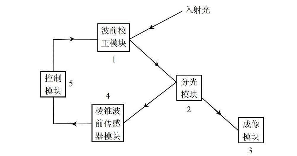
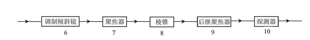
[0018] Such as figure 1 As shown, the present invention is made of wavefront correction module 1, spectroscopic module 2, imaging module 3, pyramidal wavefront sensor module 4, and control module 5; wherein the pyramidal wavefront sensor module is as figure 2 As shown, it is composed of a modulating tilting mirror 6, a focuser 7, a pyramid 8, a subsequent focuser 9 and a detector 10. The wavefront correction module is composed of a tilting mirror and a deformable mirror. The tilting mirror and the deforming mirror can adopt a piezoelectric ceramic drive structure , or MEMS structure, or liquid crystal structure.

[0019] After the light beam passes through the pyramidal wavefront sensor module 4, it will correspond to four detection sub-pupil image areas on the detector 10. In this embodiment, the number of sampling points in each sub-pupil image area is n; the closed-loop control of the adaptive optics system needs to adopt a fixed closed-loop Control modes, currently commo...


PUM


Abstract

The invention discloses an adaptive optical system based on a modulation and modulation-free combined pyramid wave-front sensor. The adaptive optical system comprises a wave-front correction module, a beam-splitting module, an imaging module, a pyramid wave-front sensor module and a control module, wherein before the adaptive optical system works, the pyramid wave-front sensor in a modulation operating mode is utilized to measure the transfer function of the system, and when the adaptive optical system works, the pyramid wave-front sensor in a modulation-free operating mode is utilized to perform closed-loop control. According to the adaptive optical system, the signal to noise ratio can be improved when the transfer function of the system is measured, and a stable transfer function matrix is obtained; and meanwhile, the detection sensitivity can be effectively improved in the closed-loop control process.

Description

technical field [0001] The invention relates to an adaptive optics system based on a modulated and non-modulated combined pyramidal wavefront sensor. Background technique [0002] Adaptive optics technology uses optoelectronic devices to measure wavefront dynamic errors in real time, uses fast electronic systems for calculation and control, and uses active devices for real-time wavefront correction, so that the optical system has the ability to automatically adapt to changes in external conditions and maintain a good working condition . Generally, an adaptive optics system includes three basic components: a wavefront sensor that detects wavefront errors, a wavefront controller that provides a wavefront correction signal, and a wavefront corrector that dynamically corrects distortion. Among them, the wavefront sensor measures the wavefront error from the target or the beacon near the target in real time. It is the core unit device in the adaptive optics system, and typically...

Claims


Application Information

Patent Timeline
Patent Type & Authority Applications(China)
IPC IPC(8): G01J9/00
Inventor 王胜千饶长辉
Owner INST OF OPTICS & ELECTRONICS - CHINESE ACAD OF SCI
Why Eureka
Try Eureka