Zoom micro lens based on piezoelectric inverse effect

A technology of inverse effect and microlens, which is applied in lens, optics, instruments, etc., can solve the problems of difficult design and manufacture of array structure, large volume, slow control response speed, etc., and achieve simple design and process manufacturing, and easy realization of array structure, the effect of broad application prospects

Inactive Publication Date: 2013-01-16
UNIV OF ELECTRONICS SCI & TECH OF CHINA
View PDF5 Cites 18 Cited by
  • Summary
  • Abstract
  • Description
  • Claims
  • Application Information

AI Technical Summary

Problems solved by technology

Liquid-type tunable microlenses usually have the characteristics of large zoom range and large numerical aperture, but at the same time have the following disadvantages: 1) The control response speed is slow, and fast control cannot be achieved; 2) The control unit is complex in structure and bulky, making it difficult to use Design and Fabricate Array Structures
Tunable liquid crystal microlens is one of the typical representatives of this type, which has many advantages such as relatively fast response speed, no mechanical movement, no surface deformation, good stability, etc., but its focal length adjustment range is small, and it usually has polarization Dependency, light loss and other disadvantages

Method used


Image

  • Zoom micro lens based on piezoelectric inverse effect
  • Zoom micro lens based on piezoelectric inverse effect
  • Zoom micro lens based on piezoelectric inverse effect

Examples


Embodiment Construction

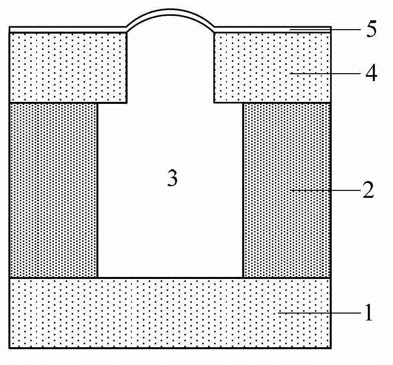
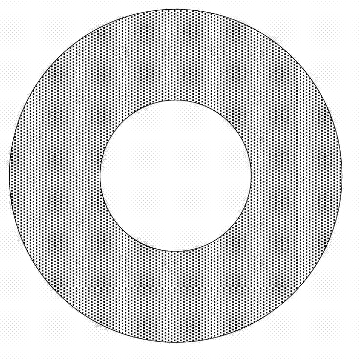
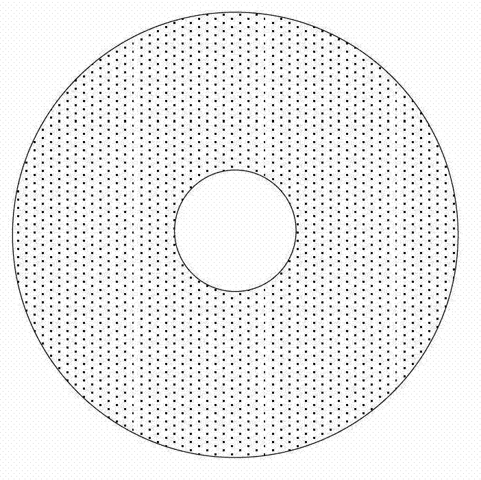
[0024] Zoom microlens based on piezoelectric inverse effect, its structure is as follows figure 1 As shown, it includes a first glass sheet 1, a piezoelectric ceramic ring 2, and a second glass sheet 4; the center of the second glass sheet 4 has a circular hole, and the surface of the second glass sheet 4 is covered with a transparent organic film 5; The piezoelectric ceramic ring 2 is clamped between the first glass sheet 1 and the second glass sheet 4, and the central circular hole of the piezoelectric ceramic ring 2 and the second glass sheet 4 remains concentric; the first glass sheet 1, the piezoelectric ceramic ring 2 and the second glass sheet 4 are sealed to form an inner space filled with a transparent liquid 3 .

[0025] For the above technical solution, the monochromatic plane wave is incident from bottom to top. When no control voltage is applied to the piezoelectric ceramic ring 2, the height of its inner cylindrical cavity is H 0 , the radius is R; when the app...


PUM


Abstract

The invention relates to a zoom micro lens based on a piezoelectric inverse effect, belonging to the technical field of optical components. The zoom micro lens comprises a first glass sheet, a piezoelectric ceramic ring and a second glass sheet, wherein a circular hole is formed in the center of the second glass sheet, and an organic thin film is covered on the second glass sheet; the piezoelectric ceramic ring is clamped between the first glass sheet and the second glass sheet; and transparent liquid is filled in an inner space formed by the sealing of the first glass sheet, the piezoelectric ceramic ring and the second glass sheet. The stretching and the shrinkage are caused to piezoelectric ceramic under the action of an electric field by feeding voltage to the piezoelectric ceramic by virtue of the piezoelectric inverse effect, so that the surface shape of the micro lens is driven to change and the regulate function of the focal length of the micro lens is realized. A focal-length-adjustable micro lens provided by the invention has multiple superiorities such as simple structure, simplicity and convenience in design and process production, easiness in realizing of array structure, fast regulation and control speeds, large regulation and control ranges and the like, and has wide application foregrounds in micro-optic systems and micro-optic electromechanical systems.

Description

technical field [0001] The invention belongs to the technical field of optical components, and relates to microlenses, especially microlenses with variable focal lengths. Background technique [0002] The design, manufacture and application of microlenses are one of the important research contents in the field of information optics. Compared with bulk lenses, microlenses have the advantages of small size, light weight, and easy arraying and integration. And many other fields have been widely used, and the application field is constantly expanding, playing an irreplaceable role in traditional optical components. In recent years, research on microlenses has developed rapidly, but the designed and manufactured microlenses and their arrays, as well as the micro-optical systems composed of these elements, are usually "static" elements or systems, that is, once these elements are designed and fabricated After completion, the optical properties and functions of its components or ...

Claims


Application Information

Patent Timeline
Patent Type & Authority Applications(China)
IPC IPC(8): G02B26/02G02B3/14
Inventor 唐雄贵童伟廖进昆陆荣国李和平刘永
Owner UNIV OF ELECTRONICS SCI & TECH OF CHINA
Why Eureka
Try Eureka