
Laser cutting path optimizing method

A path optimization and laser cutting technology, which is applied in laser welding equipment, digital control, manufacturing tools, etc., can solve the problems of reduced efficiency, slow running speed, and large amount of calculation, so as to reduce safety hazards, shorten air movement, and simple implementation Effect

Active Publication Date: 2013-01-16
上海柏楚电子科技股份有限公司
View PDF3 Cites 25 Cited by
  • Summary
  • Abstract
  • Description
  • Claims
  • Application Information

AI Technical Summary

Problems solved by technology

[0003] The path optimization methods used by general laser cutting software can be divided into two categories: one is interactive optimization, that is, the cutting path is generated manually or semi-automatically based on the user's experience. A large number of manual operations are required for large-scale graphics, which also reduces efficiency; the second is automatic optimization, and this type of method can be divided into two categories: one is to automatically sort the graphics according to a predetermined rule, such as from left to right, The cutting path generated in this way is relatively regular, and can also shorten the length of space movement, but the optimization effect of different graphics is quite different, and no rule can adapt to all situations; the second is the intelligent optimization method, combined with artificial intelligence and bionics algorithms, For example, the ant colony algorithm is used to improve the effect of path optimization. The cutting path generated by this kind of method is closer to the human way of thinking, and the length of space shift is shorter. Handle large-scale graphs
The current automatic path optimization methods are relatively prone to unnecessary single-segment long-distance air movement, which is very dangerous in the laser cutting process
In addition, the current automatic optimization method does not consider the particularity of laser cutting enough, and cannot meet the requirements of laser cutting technology in practice, and even has a large safety hazard

Method used


Image

  • Laser cutting path optimizing method
  • Laser cutting path optimizing method
  • Laser cutting path optimizing method

Examples


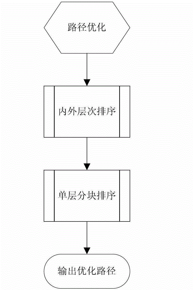
Embodiment 1

[0029] Such as Figure 7 As shown, it is a typical planar laser cutting drawing. There are several patterns in the graphics on this drawing. The number of these patterns is medium, and it is inconvenient to use interactive optimization; and the distribution of each pattern is relatively regular, but they are not aligned. The cutting of patterns The starting points are also different, and each pattern is also composed of several shaped outline patterns, which may be composed of closed lines or unclosed lines. After inputting the drawing into the laser cutting machine, the CAM software in the control system of the laser cutting machine performs the following processing steps:

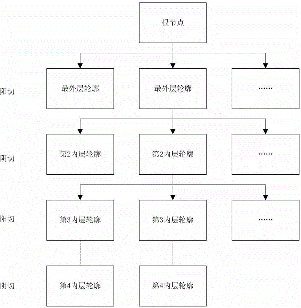
[0030] 1. Press first figure 1 The processing steps shown sort the inner and outer layers of each contour pattern: (a), take out all the contour patterns at the outermost layer in the graph, mount them under the root node of a tree, and set the fill type to Yang cut; (b) For each outline pattern of the ...


PUM


Abstract

The invention relates to the technical field of digital control laser cutters, and in particular relates to a laser cutting path optimizing method. The optimizing method is characterized by comprising the following steps: (1) inputting a graph to be cut into a control system of the laser cutter, wherein the graph is composed of at least one independent pattern, and each pattern is composed of at least one outline pattern; (2) ordering all outline patterns in the graph in accordance with inner and outer layers, so as to distinguish that whether the filling type of each outline pattern is negative cutting or positive cutting; (3) in the output graph with ordered outline patterns in inner and outer layers, ordering the outline patterns of each layer from inside to outside in sequence in a single layer and separated piece mode; and (4) outputting an optimized path. Compared with the prior art, the rate that single section long distance empty motion happens is greatly reduced, the potential safety hazard is reduced, the implementation is simple, the speed is rapid, and the efficiency in processing large graphs is higher.

Description

technical field [0001] The invention relates to the technical field of numerically controlled laser cutting machines, in particular to a laser cutting path optimization method. Background technique [0002] In the laser cutting system, CAM software is generally used for programming. The CAM software generates NC codes that can be read by machine tools through computer programming, so that the machine tools can run more accurately and efficiently, saving a lot of cost for the enterprise. A key issue to be considered when using CAM software for programming is how to improve cutting efficiency. If the cutting efficiency is too low, it will inevitably increase the processing cost, resulting in a decline in the competitiveness of enterprises. During the cutting process, the length of the space included in the path of the laser head is the bottleneck restricting the cutting efficiency. For graphics with multiple contours, different cutting sequences will produce different length...

Claims


Application Information

Patent Timeline
IPC IPC(8): G05B19/19B23K26/38
Inventor 恽筱源
Owner 上海柏楚电子科技股份有限公司
Learn More