Microstrip antenna, array consisting of microstrip antenna, array set and array set group

A technology of microstrip antenna and array, which is applied in the direction of antenna array, antenna, antenna grounding device, etc., can solve the problems of narrow frequency band of microstrip antenna, inability to form a receiving antenna system, and reduce microwave receiving efficiency, etc., and achieve the effect of easy assembly

Inactive Publication Date: 2013-01-16
UNIV OF ELECTRONICS SCI & TECH OF CHINA
View PDF7 Cites 5 Cited by
  • Summary
  • Abstract
  • Description
  • Claims
  • Application Information

AI Technical Summary

Problems solved by technology

However, there is a certain distance or gap between adjacent radiating units, which reduces the microwave receiving efficiency

Method used


Image

  • Microstrip antenna, array consisting of microstrip antenna, array set and array set group
  • Microstrip antenna, array consisting of microstrip antenna, array set and array set group
  • Microstrip antenna, array consisting of microstrip antenna, array set and array set group

Examples


Embodiment Construction

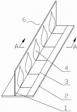
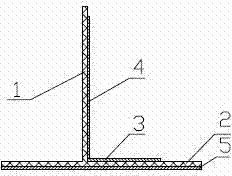
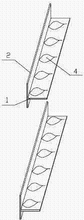
[0023] The structure of the microstrip antenna of the present invention includes a grounded dielectric plate 2 and a radiation medium plate 1 vertically arranged on the grounded dielectric plate 2 and provided with a radiation unit 4; the lower surface and the upper surface of the grounded dielectric plate 2 A metal reflective layer 5 and a microstrip feed line 3 connected to the radiating unit 4 are provided respectively, and the radiating unit 4 is lanceolate, fan-shaped, spear-shaped, heart-shaped, oval-shaped or spoon-shaped.

[0024] For the reflection coefficient diagrams of the above six shapes of radiating elements, see Figure 9 , as can be seen from the figure: the radiating unit of the present invention has a very wide operating bandwidth; the operating bandwidth is respectively: lanceolate, 2.12-19.27GHz, fan-shaped, 4.76-7.58GHz, spear-shaped 2.20- —2.74GHz, cardioid, 2.04—12.11GHz, oval, 2.25—12.45GHz, spoon, 2.17—2.78GHz.

[0025] Investigate the omnidirectiona...


PUM

PropertyMeasurementUnit
Widthaaaaaaaaaa

Abstract

The invention discloses a microstrip antenna, an array consisting of the microstrip antenna, an array set and an array set group. The microstrip antenna comprises a grounding dielectric slab, and a radiation dielectric slab vertically arranged on the grounding dielectric slab and provided with radiation elements; a metallic film and a microstrip line feed circuit connected with the radiation elements are arranged on the lower surface and the upper surface of the grounding dielectric slab respectively; and the radiation elements are lanceolate, fan-shaped, spear-shaped, heart-shaped, oval or spoon-shaped. The microstrip array is a linear array formed by the radiation elements arranged on the radiation dielectric slab by row. The microstrip array set is in a leaf mosaic structure formed by the 2-8 microstrip arrays in a manner that the radiation dielectric slabs are in parallel, the grounding dielectric slabs are in the same plane, and the radiation elements are distributed in a staggered manner. With the adoption of the microstrip antenna, the array, the array set and the array set group, the working band of a receiving antenna is widened; the radiation elements have omidirection in the plane; and the utilization ratio of microwave energy is increased.

Description

technical field [0001] The invention belongs to the technical field of microwave energy transmission, in particular to a receiving antenna for microwave energy transmission, in particular to a microstrip antenna and an array, an array group, and an array group composed of the microstrip antenna. Background technique [0002] Microwave Power Transmission (MPT: Microwave Power Transmission) is to transmit energy directly from the transmitting end to the receiving end through free space. Generally, microwave energy transmission is divided into three steps: 1) Direct current (DC) power is converted into radio frequency energy, and transmitted through the transmitting antenna The radio frequency energy is emitted; 2) The radio frequency energy is transmitted at a certain distance in space; 3) The energy is collected at the receiving end and converted into direct current (DC) power. Since the microwave transmission loss is only atmospheric loss, rain attenuation, and shelter l...

Claims


Application Information

Patent Timeline
IPC IPC(8): H01Q13/08H01Q1/38H01Q1/48H01Q21/00
Inventor 王朗杨顺李乐伟
Owner UNIV OF ELECTRONICS SCI & TECH OF CHINA
Why Eureka
Try Eureka