Power supply system, power supply system control device, power supply system operation method and power supply system control method

A technology of power supply and control device, applied in battery circuit device, circuit device, load supply circuit, etc., can solve the problem that the power generation system cannot be started, and achieve the effect of improving startability and stopability

Active Publication Date: 2013-01-16
PANASONIC INTELLECTUAL PROPERTY MANAGEMENT CO LTD
View PDF6 Cites 7 Cited by
  • Summary
  • Abstract
  • Description
  • Claims
  • Application Information

AI Technical Summary

Problems solved by technology

[0007] However, the power generation system disclosed in the above-mentioned patent document 1 has the following first problem: when the power generation system is started, there is a possibility that the upper limit value (for example, contract power) of the electric power supplied from the electric power system will be exceeded. If the state where the power consumption of the external electric load is large continues, the power generation system cannot be started during this period.

Method used


Image

  • Power supply system, power supply system control device, power supply system operation method and power supply system control method
  • Power supply system, power supply system control device, power supply system operation method and power supply system control method
  • Power supply system, power supply system control device, power supply system operation method and power supply system control method

Examples


Embodiment approach 1

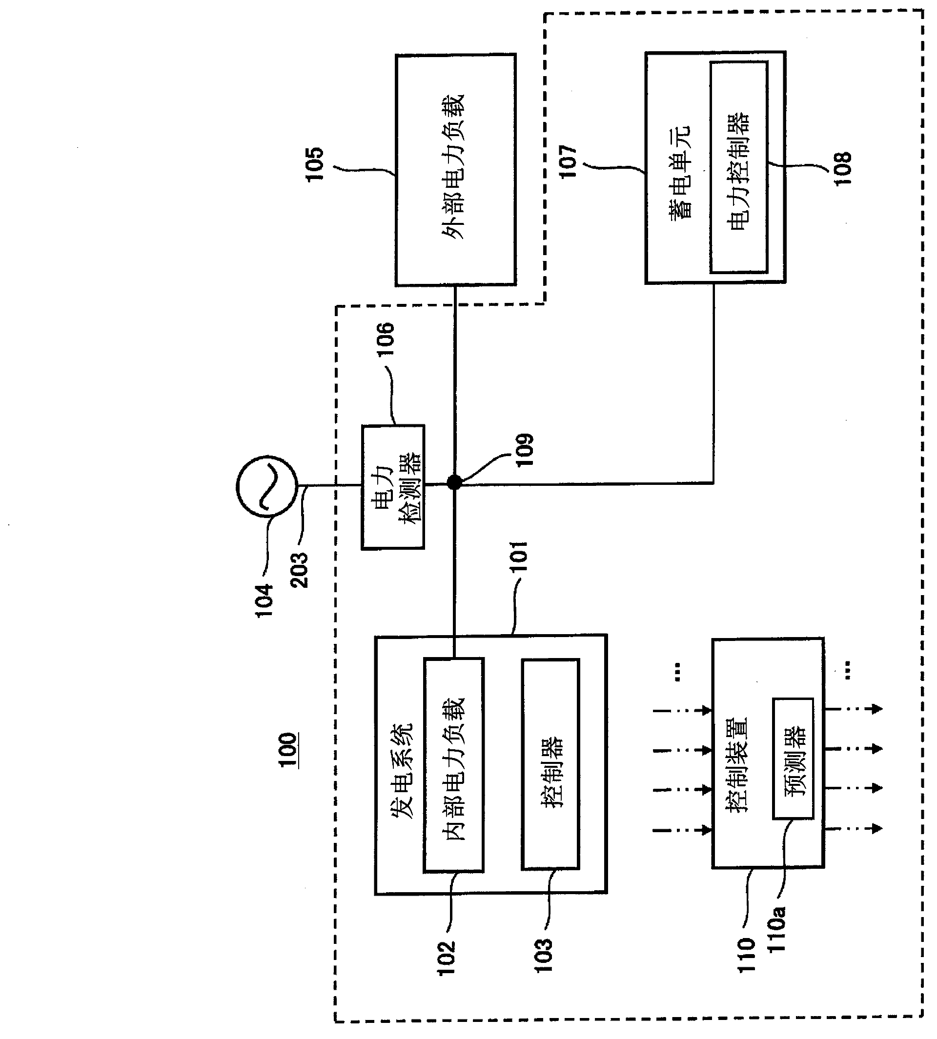
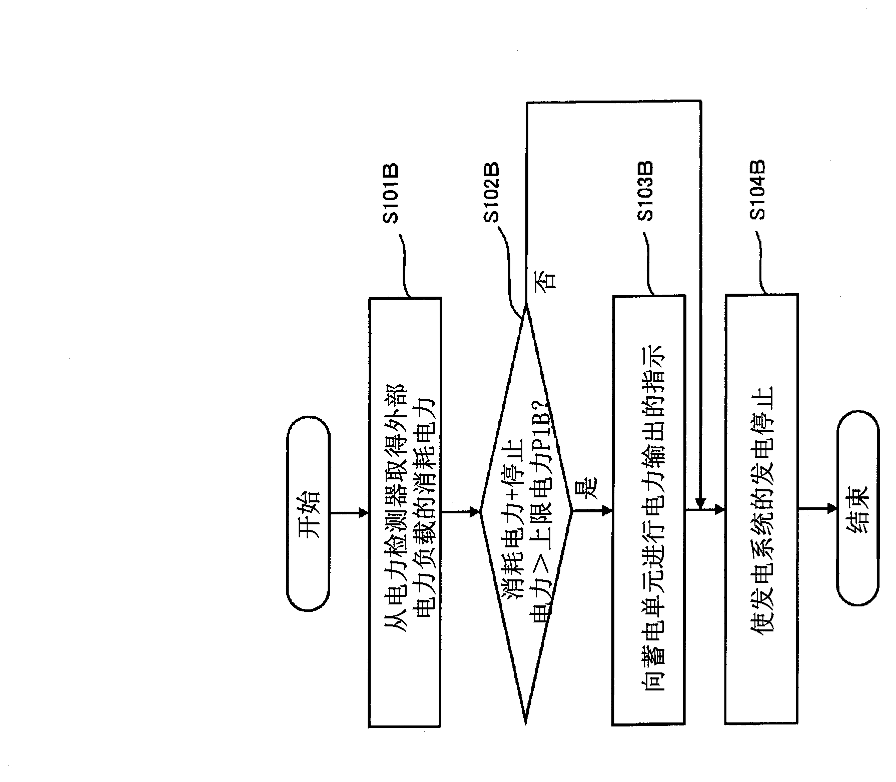
[0070] The power supply system according to Embodiment 1 includes: a power generation system; an electric storage unit that supplies power to the power generation system and an external electric load; and a control device (control device of the power supply system) that executes the first control and the second control At least one of the control methods is configured, wherein the first control is controlled in such a manner that the total of the starting power of the power generation system and the power consumption of the external electric load exceeds the amount that can be received from the power system when the power generation system is predicted to be started. In the case of the upper limit power of electric power, the electric power of the electric storage unit is supplied to at least one of the power generation system and the external electric load in such a manner that the power supplied from the electric power system does not exceed the upper limit power; the second c...

Deformed example 1

[0111] The power supply system according to Modification 1 is an example in which the power generation system is a fuel cell system.

[0112] Figure 3A It is an example of a block diagram schematically showing a schematic configuration of a power generation system of a modified example of the power supply system according to the first embodiment.

[0113] Such as Figure 3A As shown, the power generation system 101 of Modification 1 is a fuel cell system, and includes, as an internal electric load, an electric heater for heating up components of the fuel cell system when the fuel cell system is started. Specifically, the power generation system (fuel cell system) 101 of Modification 1 includes a hydrogen generator 11, an oxidant gas supplier 12, a fuel cell 13, a cooling medium container 14, an electric heater 15, a cooling medium sender 16, and a control system. device 103.

[0114] The hydrogen generator 11 includes a reformer 1 , a CO reducer 2 , and an electric heater ...

Deformed example 2

[0129] The power supply system according to Modification 2 is another example in which the power generation system is a fuel cell system.

[0130] Figure 3B It is an example of a block diagram schematically showing a schematic configuration of a power generation system according to Modification 2 of the power supply system of Embodiment 1. FIG.

[0131] Such as Figure 3B As shown, the power generation system 101 of Modification 2 is basically the same in structure as the fuel cell system of Modification 1, but differs in that it further includes a recovered water container 17 and a feeder 18 . In addition, the electric heater 15 may also be provided in the recovered water container 17 .

[0132] The recovered water container 17 is a container for storing recovered water from exhaust gas discharged in the fuel cell system 101 . The exhaust gas may be any exhaust gas, for example, at least one of fuel gas and oxidant gas exhausted from the fuel cell 13 , combustion exhaust ...


PUM


Abstract

The disclosed power supply system is provided with a generation system (101), a power storage unit (107) which supplies power to the generation system (101) and to an external power load (105), and a control device (110) which, if it is predicted that the sum of the startup power of the generation system (101) at startup of said generation system (101) and the power consumed by the external power load (105) and/or the sum of the stopping power of the generation system (101) at stopping of generation by the generation system (101) and the power consumed by the external power load (105) will exceed the upper power limit of what can be received from a power system (104), performs controls such that power of the power storage unit (107) be supplied to the generation system (101) and/or the external power load (105) so that the amount of power supplied from the power system (104) does not exceed the upper power limit.

Description

technical field [0001] The present invention relates to a power supply system including a power generation system, a storage battery that supplies power to the power generation system and an external electric load, an operating method of the power supply system, and a control method of the power supply system. Background technique [0002] Conventionally, in power generation systems such as fuel cells and gas engines, etc., if the starting power required to start the power generation system and the power consumption of the external power load of the power generation system exceed the contract power, the circuit breaker will drop, resulting in the failure of the power generation system. The starter had to be stopped. In order to prevent the breaker from falling when the power generation system is started, a power generation system has been proposed that does not start when the sum of the starting power of the power generation system and the power consumption of the external e...

Claims


Application Information

Patent Timeline
Patent Type & Authority Applications(China)
IPC IPC(8): H02J3/32H02J3/38H02J3/46H02J7/00
CPCH02J7/0063H02J3/32H02J3/46
Inventor 鹈饲邦弘金子广明
Owner PANASONIC INTELLECTUAL PROPERTY MANAGEMENT CO LTD
Why Eureka
Try Eureka