
Distortion correction method applied to flat-panel charge coupling device (CCD) detector

A distortion correction and detector technology, applied in the fields of medical digital image processing and digital image processing, can solve the problems of unfavorable installation and transportation, light source attenuation, high product cost, and achieve the effect of appropriate calculation and high efficiency.

Active Publication Date: 2013-01-23
SHENZHEN ANGELL TECH
View PDF1 Cites 9 Cited by
  • Summary
  • Abstract
  • Description
  • Claims
  • Application Information

AI Technical Summary

Problems solved by technology

[0002] At present, the single CCD (charge coupling device) detectors on the market have the following defects: First, the single CCD detector needs to use a super wide-angle lens, so the system has a long collection optical path, which leads to a large volume and weight of the product, which is not conducive to installation and transportation and other engineering operations; secondly, due to the influence of lens and X-ray characteristics, the collected images are brighter in the center and gradually darken along the surrounding direction, which affects the quality of medical images and the spatial resolution of images. Thirdly, due to the long acquisition optical path, the attenuation of the light source is serious, and the image is in a weak light environment. In order to make up for the loss, the dose of X-rays needs to be increased; in addition, the single CCD detector uses a large-resolution CCD and super Wide-angle lens and other expensive components, so the cost of the product is relatively high, and the acquisition system has very strict requirements on the working environment
The calculation of this method is small, the engineering practicability is strong, and it has strong robustness; but before the imaging mode of the camera is obtained, the imaging model and characteristics of the camera must be evaluated in advance

Method used


Image

  • Distortion correction method applied to flat-panel charge coupling device (CCD) detector
  • Distortion correction method applied to flat-panel charge coupling device (CCD) detector
  • Distortion correction method applied to flat-panel charge coupling device (CCD) detector

Examples


Embodiment Construction

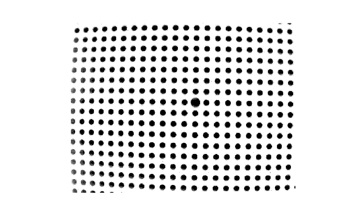
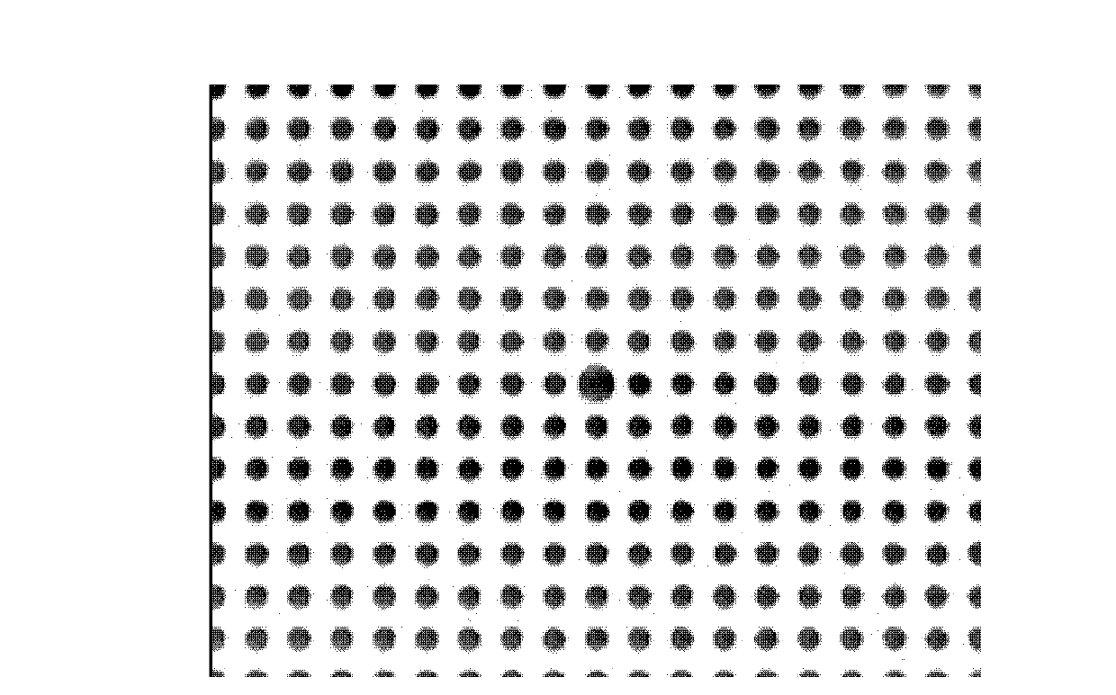
[0030] Figure 1(a) shows the original image of the dot template, and the image has obvious distortion. Using the above distortion scheme, the experimental results are shown in Figure 1(b). It can be seen from the figure that the image has no distortion and no obvious loss. Figure 2(a) is corrected for distortion using the distortion coefficient of the dot template, and the result is shown in Figure 2(b). The same image has almost no distortion and no obvious loss.

[0031] For a given lens, its optical distortion remains essentially unchanged. Therefore, the calibration method can be used to calibrate its optical distortion properties. Specifically, the method of using the dot template is adopted, and the distortion correction of the dot template image is realized through a series of image processing by taking the dot template image, thereby obtaining the optical distortion parameters of the lens, and realizing the calibration of the optical distortion of the lens. When shoot...


PUM


Abstract

The invention provides a distortion correction method applied to a flat-panel charge coupling device (CCD) detector. The method comprises the following steps of: acquiring a dot template image by the flat-panel CCD detector; acquiring the neighboring relation of various dots in the dot template image by a grid search method; constructing quadrilaterals by using circle centers of each four dots so as to construct dot quadrilateral grids of the dot template image; and finally, acquiring distortion factors through coordinate transformation, and realizing the correction of a medical image by using the distortion factors and a cubic interpolation method. By the method, the solving operation amount of the distortion factors is appropriate, so that the efficiency is high; and before an imaging mode of a camera is obtained, an imaging model and the characteristics of the camera are not required to be pre-evaluated.

Description

technical field [0001] The invention belongs to the field of digital image processing, in particular to the field of medical digital image processing. Background technique [0002] At present, the single CCD (charge coupling device) detectors on the market have the following defects: First, the single CCD detector needs to use a super wide-angle lens, so the system has a long collection optical path, which leads to a large volume and weight of the product, which is not conducive to installation and transportation and other engineering operations; secondly, due to the influence of lens and X-ray characteristics, the collected images are all brighter in the center and gradually darken along the surrounding direction, which affects the quality of medical images and the spatial resolution of images. Thirdly, due to the long acquisition optical path, the light source attenuation is serious, and the image is in a weak light environment. In order to make up for the loss, the dose o...

Claims


Application Information

Patent Timeline
IPC IPC(8): A61B6/00
Inventor 李学军卢湖川杜碧王栋姜维
Owner SHENZHEN ANGELL TECH
Learn More