

Magnetorheological damper for automotive suspension
A magnetorheological damper, automobile suspension technology, applied in the direction of suspension, elastic suspension, vehicle parts, etc., can solve the problems of fixed performance and inability to adjust the automobile suspension, so as to improve the handling stability and reliability. , The effect of not easy to corrode and fail
- Summary
- Abstract
- Description
- Claims
- Application Information
AI Technical Summary
Problems solved by technology
Method used
Image

Examples
Embodiment 1
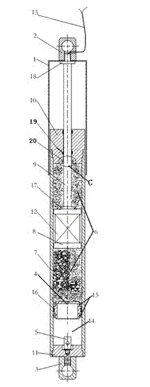
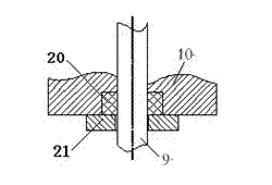
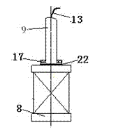
[0035] Such as figure 1 The shown embodiment proposes a magneto-rheological damper for automobile suspension, including a single rod hydraulic cylinder, a dust cover 1, an upper connector 2, a lower connector 3, a free piston 4 and a one-way inflation valve 5, There is a magnetorheological fluid 6 in the cavity of the single-rod hydraulic cylinder, and the single-rod hydraulic cylinder includes a cylinder body 7, a piston 8 disposed inside the cylinder body, and a piston rod 9 disposed on the piston. End caps are provided, and the end caps are provided with two upper end caps 10 and lower end caps 11 respectively, which are installed on both ends of the cylinder body 7 respectively, and the piston rod 9 protrudes outside the cylinder body 7 through the upper end cap 10 The middle part of the piston 8 is wound with an excitation coil 12, the piston 8 and the inner wall of the cylinder body 7 are provided with a gap for the magneto-rheological fluid 6 to flow back and forth in t...
Embodiment 2
[0042] as attached Figure 4 As shown, as another embodiment of the present invention, the difference from the first embodiment lies in that a coil spring 23 is provided between the free piston 4 and the lower end cover 11 in the volume compensation chamber 14 to provide restoring force.
Embodiment 3
[0044] As shown in the drawings, as another embodiment of the present invention, the difference from the first embodiment is that the replaced volume compensation chamber 14 is not filled with high-pressure gas, and a one-way inflation valve is not installed inside the lower end cover 11. 5. A coil spring 23 is used between the free piston 4 and the lower end cover 11 to provide a restoring force, and an air hole 24 is opened on the lower end cover 11 .
[0045] In this embodiment, a magneto-rheological damper for automobile suspension is respectively connected to the frame and axle of the automobile through the upper and lower connectors, and is connected in parallel with the suspension spring, which can achieve the following beneficial effects: the magneto-rheological damper for automobile suspension The rheological damper has the advantages of simple structure, reliable performance, small space occupation, rapid response, and large damping force. The dynamic characteristics...
PUM
 Abstract
Description
Claims
Application Information