Reflection enhancement structure of OLED (Organic Light Emitting Diode) anode and reflection enhancement structure of OLED cathode

A technology of anode and cathode, which is applied in the manufacture of electrical components, electrical solid devices, semiconductor/solid devices, etc., and can solve problems such as high cost and Ag pollution

Inactive Publication Date: 2013-01-23
KUNSHAN NEW FLAT PANEL DISPLAY TECH CENT
View PDF4 Cites 22 Cited by
  • Summary
  • Abstract
  • Description
  • Claims
  • Application Information

AI Technical Summary

Problems solved by technology

Therefore, Ag is usually used as the anode, but Ag will bring more serious pollution problems and higher costs

Method used


Image

  • Reflection enhancement structure of OLED (Organic Light Emitting Diode) anode and reflection enhancement structure of OLED cathode
  • Reflection enhancement structure of OLED (Organic Light Emitting Diode) anode and reflection enhancement structure of OLED cathode
  • Reflection enhancement structure of OLED (Organic Light Emitting Diode) anode and reflection enhancement structure of OLED cathode

Examples


Embodiment Construction

[0035] First, the basic optical principles are introduced as follows:

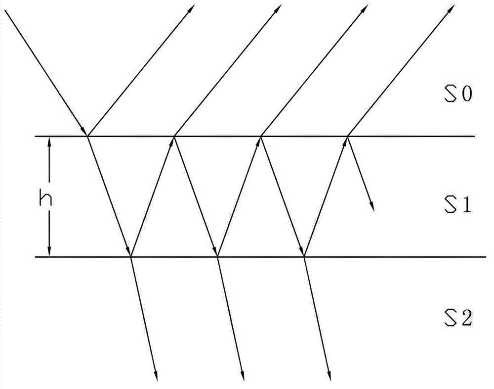
[0036] like figure 1 As shown, the light from the refractive index n 0 The medium S0 passes through the refractive index n 1 , a dielectric film S1 with a thickness of h incident to the refractive index n 2 The substrate S2, the reflectivity formula on the dielectric film S1 is as follows:

[0037]

[0038] Where: R is the reflectivity on the dielectric film S1;

[0039] is the optical thickness of the dielectric film S1.

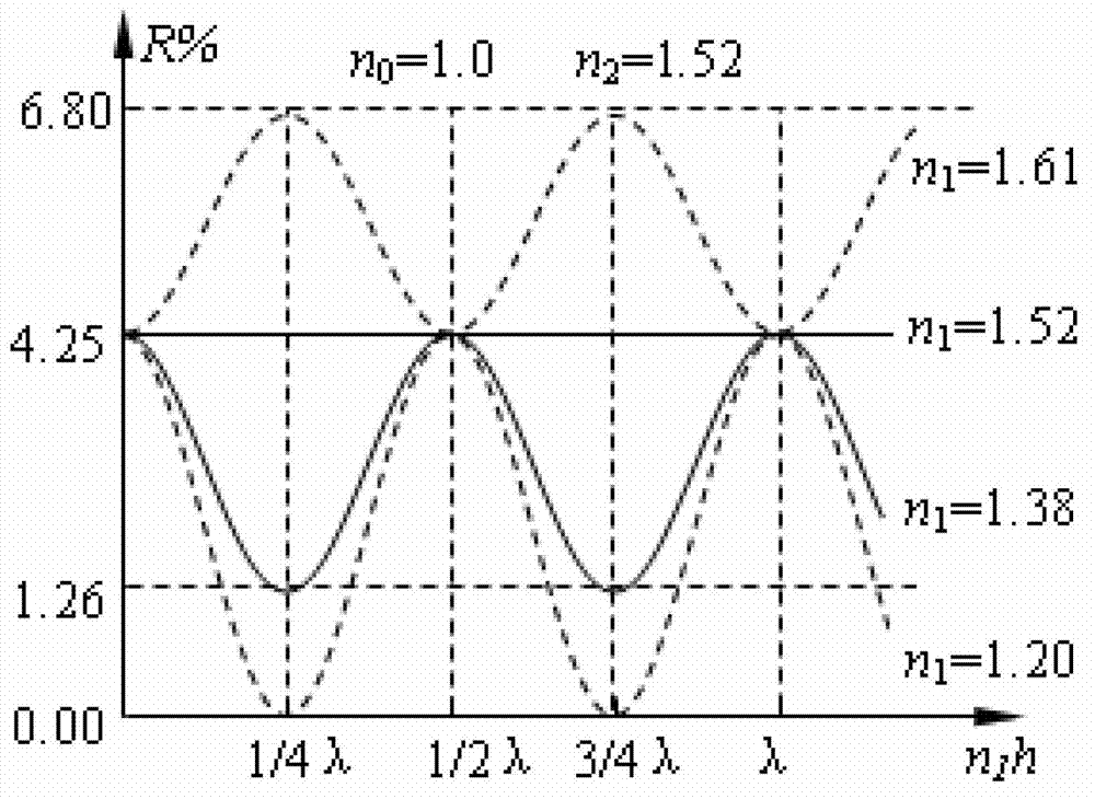
[0040] The above formula shows that for a certain substrate S2 and dielectric film S1, n 1 and n 2 is a constant, R varies with (i.e. with n 1 h) change.

[0041] Below: crown brand K9 glass (refractive index n 2 =1.52) the surface is coated with a thin film (refractive index n 1 ), light of wavelength λ travels from air (refractive index n 0 ) in normal incidence as an example, for a given wavelength λ and different refractive index n 1 Th...


PUM


Abstract

The invention provides a reflection enhancement structure of anOLED (Organic Light Emitting Diode) anode and a reflection enhancement structure of an OLED cathode. A reflection enhancement film with electroconductive properties are added in an anode structure or a cathode structure of an OLED, and the refractive index of the reflection enhancement film is more than the refractive rate of the two adjacent material layers, so that a reflection enhancement effect can be achieved.

Description

technical field [0001] The invention relates to an OLED anode or cathode structure, which can be applied to a top-emitting or bottom-emitting AMOLED structure. Background technique [0002] Compared with the current mainstream flat panel display technology Thin Film Transistor Liquid Crystal Display (TFT-LCD), Active Matrix Organic Light Emitting Diode Display (AMOLED) has the advantages of high contrast, wide viewing angle, low power consumption, lighter and thinner, etc., and is expected to become the successor to LCD. The subsequent next-generation flat panel display technology is one of the most concerned technologies in the current flat panel display technology. [0003] An organic light-emitting diode (OLED) display is an active light-emitting device, which can be used not only as a pixel constituting an AMOLED display, but also as a light source for solid-state lighting. Therefore, the improvement of OLED performance, especially the improvement of efficiency directly...

Claims


Application Information

Patent Timeline
Patent Type & Authority Applications(China)
IPC IPC(8): H01L51/52
Inventor 陈红邱勇黄秀颀
Owner KUNSHAN NEW FLAT PANEL DISPLAY TECH CENT
Why Eureka
Try Eureka