Forced finned straight pipe condensation heat-supply heat exchanger

A technology of heat exchangers and fins, applied in the field of forced finned straight tube condensation heat supply heat exchangers, can solve the problems of small volume, insufficient heat exchange in the flow path of flue gas, etc., to improve heat exchange efficiency and facilitate batch production The effect of streamlining production and reducing production difficulty

Active Publication Date: 2013-01-30
SUZHOU CQ HEAT EXCHANGER
View PDF4 Cites 15 Cited by
  • Summary
  • Abstract
  • Description
  • Claims
  • Application Information

AI Technical Summary

Problems solved by technology

[0013] Therefore, the technical problem to be solved by the present invention is how to overcome the problem of insufficient heat exchange in the flue gas flow path caused by the insufficient design of the heat exchanger structure in the prior art, and how to improve the structure of the heat transfer surface to increase the heat exchange area and improve the heat transfer efficiency. The purpose of thermal efficiency is to make the boiler smaller and occupy a smaller volume under the same power, and how to skillfully combine the air preheater into the heat exchanger, so as to perform secondary heat exchange and improve air intake The initial temperature while further reducing the exhaust gas temperature

Method used


Image

  • Forced finned straight pipe condensation heat-supply heat exchanger
  • Forced finned straight pipe condensation heat-supply heat exchanger
  • Forced finned straight pipe condensation heat-supply heat exchanger

Examples


Embodiment Construction

[0046] Embodiments of the present invention are described in detail below, examples of which are shown in the accompanying drawings, which are only used to explain the present invention and are not to be construed as limiting the present invention.

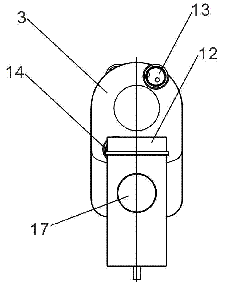
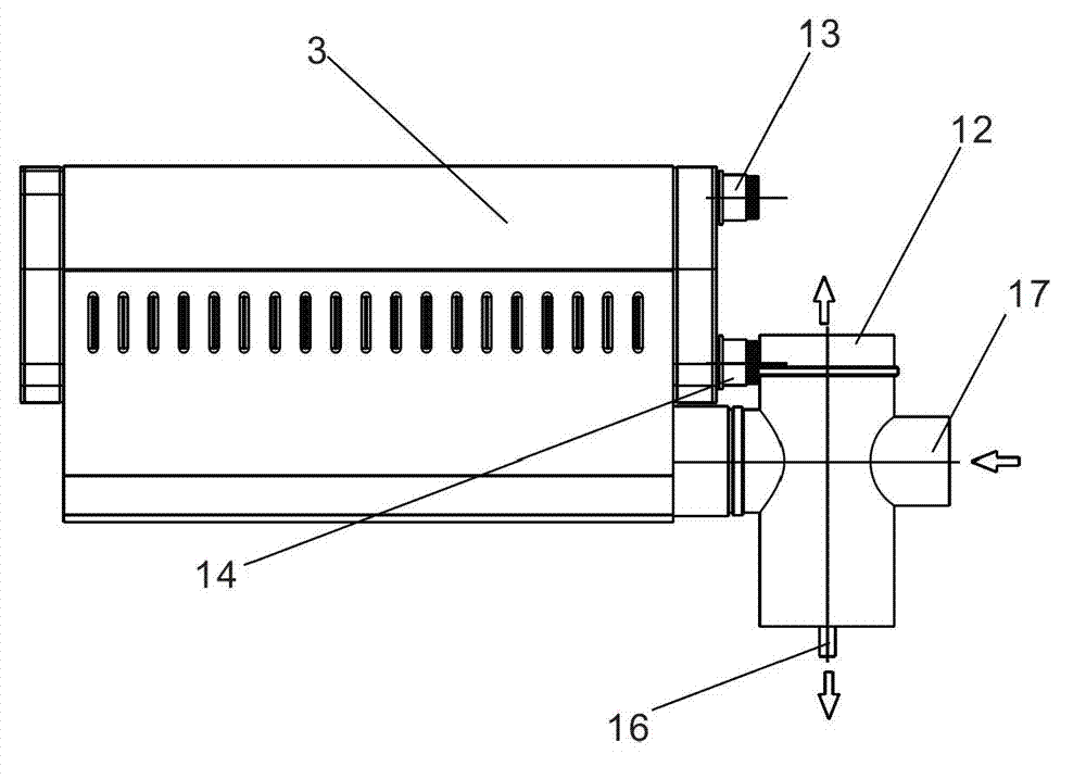
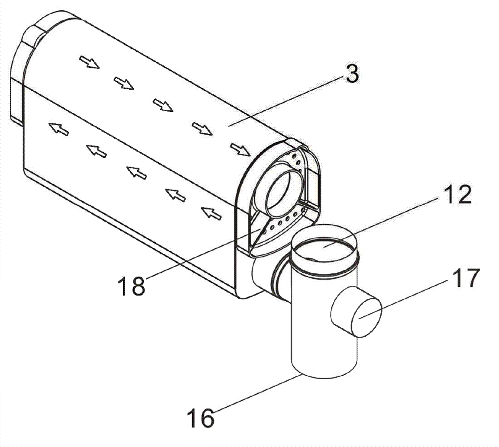
[0047] Such as Figure 1 to Figure 16 As shown, it includes: front jellyfish tube 1, front baffle plate 2, shell 3, finned straight tube bundle 4, outer deflector 5, burner 6, inner deflector 7, a plurality of closely arranged finned straight tubes 8. Rear jellyfish pipe 9, rear baffle 10, air preheater 11, smoke outlet 12, water outlet 13, water inlet 14, smoke exhaust pipe 15, condensate outlet 16, air inlet 17, partition 18.

[0048] refer to Figure 1 ~ Figure 3 A forced finned straight tube condensing heat supply heat exchanger according to an embodiment of the present invention is described. Such as figure 1 , figure 2 and image 3 As shown, a forced finned straight tube condensing heat exchanger includes a shell 3, a ...


PUM


Abstract

The invention discloses a forced finned straight pipe condensation heat-supply heat exchanger, which comprises a shell, a combustor and a plurality of finned straight pipes, wherein the combustor is positioned on the upper part of the shell; the periphery of the combustor is provided with a group of finned straight pipe bundles consisting of a plurality of finned straight pipes which are tightly and uniformly distributed along the circumference; a smoke exhaust pipeline which consists of the shell and a plurality of tightly arranged finned straight pipes is arranged below the combustor; the smoke exhaust pipeline is emptied through a smoke outlet; two ends of the finned straight pipes are respectively front water main pipes and rear water main pipes; clapboards are arranged in the rear water main pipes; the rear water main pipes are separated into a water inlet area and a water outlet area through the clapboards; and water flow enters part of the finned straight pipes through the water inlet area, reaches the front water main pipes and enters the water outlet area of the rear water main pipes through the other part of the finned straight pipes. The inwards folded finned straight pipes serve as basic elements of the forced finned straight pipe condensation heat-supply heat exchanger, and the heat exchange efficiency is obviously improved.

Description

technical field [0001] The invention belongs to the field of thermal equipment, in particular to a forced-finned straight-tube condensing heat-supply heat exchanger. Background technique [0002] As early as the Middle East oil crisis in the 20th century, in order to save energy, a condensing boiler with high thermal efficiency was developed in Europe. Its remarkable feature is that the thermal efficiency is more than 10% higher than that of conventional design boilers. Since the exhaust gas temperature of the boiler is lowered above the dew point, a large amount of water vapor in the flue gas condenses and releases the latent heat of vaporization, which has obvious energy-saving effects. The condensing heat exchanger used in the condensing boiler is developed according to its principle. . [0003] The heat available for gas combustion includes two parts: the sensible heat of the flue gas and the latent heat of water vapor in the flue gas. The ordinary heat exchanger is li...

Claims


Application Information

Patent Timeline
Patent Type & Authority Applications(China)
IPC IPC(8): F24H8/00F24H9/00
CPCY02B30/102F24H1/403F24H1/406F24H1/445F24H3/087F24H8/006F24H9/0084Y02B30/00
Inventor 崔树庆
Owner SUZHOU CQ HEAT EXCHANGER
Why Eureka
Try Eureka