Pavement water accumulation and ice accumulation detection method and apparatus thereof

A detection method and area technology, applied in the field of optical communication, can solve problems such as expensive, difficult to popularize and use, and limited sampling space, and achieve the effects of high application value, stable work, and wide detection range

Inactive Publication Date: 2013-01-30
山东海润数聚科技有限公司
View PDF3 Cites 17 Cited by
  • Summary
  • Abstract
  • Description
  • Claims
  • Application Information

AI Technical Summary

Problems solved by technology

[0002] Traditional road condition monitors mainly use the principle of different absorption rates of infrared rays or microwaves on dry roads and ice and snow roads to detect road conditions. This detection method has the following disadvantages: limited sampling space, expensive, and cannot be used in a large area along the road. Layout and it is difficult to reflect the real situation of the entire road section
At present, Hiroshi FUKUI, Junichi TAKAGI et al. propose a method using image processing (see: Hiroshi Fukui, Junichi Takagi, Yoshiro Murata and Masashi Takeuchi.An Image Processing Method To Detect RoadSurface Condition Using Optical Spatial Frequency[J].IEEEConference on Intelligent Transportation System , 1997: 1005-1009.) to detect road conditions. This detection method uses the maximum full width and spatial frequency distribution of monitoring images to distinguish different road conditions. However, this method requires artificial light as an auxiliary and can only be used at night , and the position of the light source and the CCD camera is fixed, resulting in a small detection range, making it difficult to popularize and use
[0003] Currently, Y...

Method used


Image

  • Pavement water accumulation and ice accumulation detection method and apparatus thereof
  • Pavement water accumulation and ice accumulation detection method and apparatus thereof
  • Pavement water accumulation and ice accumulation detection method and apparatus thereof

Examples


Embodiment Construction

[0029] Hereinafter, the present invention will be described in detail with reference to the drawings and examples. It should be noted that, in the case of no conflict, the embodiments in the present application and the features in the embodiments can be combined with each other.

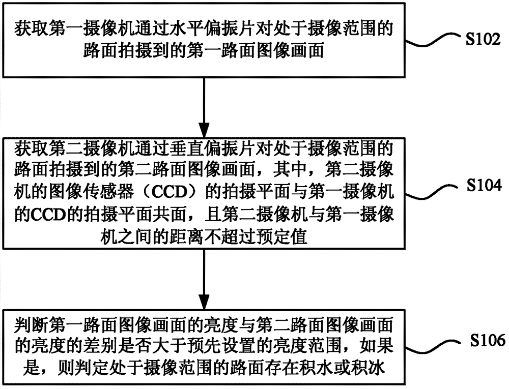
[0030] figure 1 It is a flowchart of a method for detecting ice accumulation on road surface water according to an embodiment of the present invention, as figure 1 As shown, the method mainly includes the following steps (step S102-step S106):

[0031] Step S102, acquiring a first road surface image captured by the first camera on the road within the imaging range through the horizontal polarizer;

[0032] In the embodiment of the present invention, the first camera may generate a first road surface image frame according to the first reflected light passing through the horizontal polarizer, and then upload the first road surface image frame to a designated image processing device.

[0033] Step S1...


PUM


Abstract

The present invention discloses a pavement water accumulation and ice accumulation detection method and an apparatus thereof. The method comprises: acquiring a first pavement image picture of a pavement positioned in an imaging range, wherein the first pavement image picture is captured by a first camera through a horizontal polarizer; acquiring a second pavement image picture of the pavement positioned in the imaging range, wherein the second pavement image picture is captured by a second camera through a vertical polarizer, wherein the imaging plane of an image sensor (CCD) of the second camera and the imaging plane of an CCD of the first camera are coplanar, and a distance between the second camera and the first camera does not exceed a predetermined value; and determining whether difference between brightness of the first pavement image picture and brightness of the second pavement image picture is larger than a predetermined brightness range, wherein the case that water accumulation or ice accumulation exists on the pavement positioned in the imaging range is determined if the difference between the brightness is larger than the predetermined brightness range. The apparatus can be promoted in the existing pavement detection camera, and has advantages of simple modification, low modification cost, and no influence on the original system.

Description

technical field [0001] The invention relates to the field of optical communications, in particular to a method and device for detecting water and ice accumulation on road areas. Background technique [0002] Traditional road condition monitors mainly use the principle of different absorption rates of infrared rays or microwaves on dry roads and ice and snow roads to detect road conditions. This detection method has the following disadvantages: limited sampling space, expensive, and cannot be used in a large area along the road. The layout and it is difficult to reflect the real situation of the entire road section. At present, Hiroshi FUKUI, Junichi TAKAGI et al. propose a method using image processing (see: Hiroshi Fukui, Junichi Takagi, Yoshiro Murata and Masashi Takeuchi.An Image Processing Method To Detect RoadSurface Condition Using Optical Spatial Frequency[J].IEEEConference on Intelligent Transportation System , 1997: 1005-1009.) to detect road conditions. This detec...

Claims


Application Information

Patent Timeline
IPC IPC(8): G01C11/08
CPCG01N21/21G01J1/1626G01C11/08G01J1/0429
Inventor 付强李勃张震玮陈启美何军江登表
Owner 山东海润数聚科技有限公司
Why Eureka
Try Eureka