Sliding-touch dimming LED (light-emitting diode) flashlight

A technology of LED flashlight and sliding touch, which is applied in the direction of light source, electric light source, electric light circuit layout, etc., which can solve the problems of expensive, difficult to achieve waterproof design, complicated circuit, etc., and achieve aesthetics, good sealing, and convenient operation Effect

Inactive Publication Date: 2013-01-30
WUYI UNIV
View PDF11 Cites 5 Cited by
  • Summary
  • Abstract
  • Description
  • Claims
  • Application Information

AI Technical Summary

Problems solved by technology

This solution needs to use a mechanical mechanism, such as a rotating ring, to adjust the distance between the magnet and the Hall element. The moving process is prone to wear and mechanical failure, and it is difficult to achieve a waterproof design; The circuit is complex and expensive

Method used


Image

  • Sliding-touch dimming LED (light-emitting diode) flashlight
  • Sliding-touch dimming LED (light-emitting diode) flashlight
  • Sliding-touch dimming LED (light-emitting diode) flashlight

Examples


Embodiment Construction

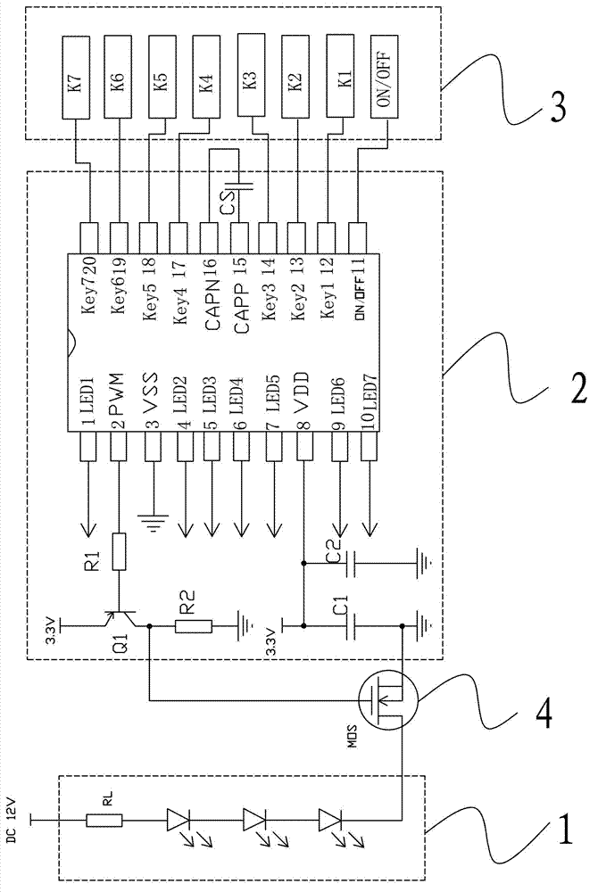
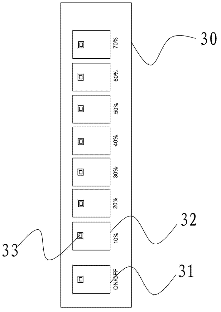
[0014] refer to figure 1 , a sliding touch-type dimming LED flashlight, comprising an LED string 1, a circuit driving unit 2 and a dimming control unit 3, the input end of the circuit driving unit 2 is connected to the dimming control unit 3, and its output end is connected to the LED string 1 , the dimming control unit 3 uses a sliding touch sensing bar 30 as a control component, the sliding touch sensing bar 30 is a capacitive touch sensing bar, and adopts a dimming technology without mechanical moving parts, which makes the operation more convenient and can avoid parts Wear and tear, and at the same time, it is well sealed, waterproof and dustproof, and has strong practicality.

[0015] Specifically, a plurality of touch capacitive switches 31, 32 are provided on the sliding touch sensing bar 30, and the inside thereof is a switch based on a capacitor. Touching a capacitor with a conductive object (such as a finger) can change the capacitance, and this change will be built-...


PUM


Abstract

The invention discloses a sliding-touch dimming LED (light-emitting diode) flashlight, comprising an LED string, a circuit driving unit and a dimming control unit, wherein the input end of the circuit driving unit is connected with the dimming control unit, and the output end of the circuit driving unit is connected with the LED string; the dimming control unit takes a sliding touch sensing bar, which is a capacitive touch sensing bar, as a control element; and the circuit driving unit implements the dimming of LEDs by outputting corresponding PWM (Pulse-Width Modulation) signals which control the duty ratio of an external MOS (Metal Oxide Semiconductor) transistor switch. By adopting a dimming technology without mechanical moving elements, the sliding-touch dimming LED flashlight is more convenient and easier to operate, and the elements can be free from abrasion and faults; and the sliding-touch dimming LED flashlight has a good sealing property, has waterproof and dustproof functions, and is high in practicability.

Description

technical field [0001] The invention relates to an LED flashlight, in particular to a sliding touch-type dimming LED flashlight. Background technique [0002] At present, the LED flashlight dimming technology adopts magnetically controlled stepless dimming. The principle is to adjust the distance between the Hall element and the magnet, so that the Hall element can sense the strength of the magnetic field to change the size of the output signal, and then through the single-chip microcomputer (MCU). ) to control the duty cycle of the PWM signal after AD conversion to realize the dimming of the LED. This solution needs to use a mechanical mechanism, such as a rotating ring, to adjust the distance between the magnet and the Hall element. The moving process is prone to wear and mechanical failure, and it is difficult to achieve a waterproof design; Circuits are complex and expensive. Contents of the invention [0003] In order to solve the above problems, the present inventi...

Claims


Application Information

Patent Timeline
Patent Type & Authority Applications(China)
IPC IPC(8): H05B37/02
Inventor 周党培王忆
Owner WUYI UNIV
Why Eureka
Try Eureka