
Method for welding transparent material

A transparent material and combined technology, applied in welding equipment, laser welding equipment, metal processing equipment, etc., can solve the problems of welding efficiency limitation, low peak power, low power, etc., and achieve the goal of improving welding efficiency, realizing welding and reducing costs Effect

Inactive Publication Date: 2013-02-06
TIANJIN UNIV
View PDF6 Cites 12 Cited by
  • Summary
  • Abstract
  • Description
  • Claims
  • Application Information

AI Technical Summary

Problems solved by technology

However, the problem of connecting transparent materials has not been well solved. Now, chemical adhesives or intermediate layers are mainly used. Such connections cannot guarantee good mechanical properties, good thermal stability and chemical stability.
However, ultrashort pulse laser has high cost and low power, and the welding efficiency is limited, which has become the bottleneck of practical application.
[0004] Long-pulse laser technology has been maturely used in industrial production, but the peak power is low, and it is not enough to achieve multi-photon absorption (ionization) after focusing inside the transparent material. Only metal impurities in the transparent material can be used to absorb long-pulse laser, while The distribution of metal impurities cannot be effectively controlled, so the long-pulse laser cannot effectively process the internal material of the material without adding an absorbing layer, and can only process the surface of the material

Method used


Image

  • Method for welding transparent material
  • Method for welding transparent material
  • Method for welding transparent material

Examples


Embodiment Construction

[0022] In order to make the object, technical solution and advantages of the present invention clearer, the implementation manner of the present invention will be further described in detail below in conjunction with the accompanying drawings.

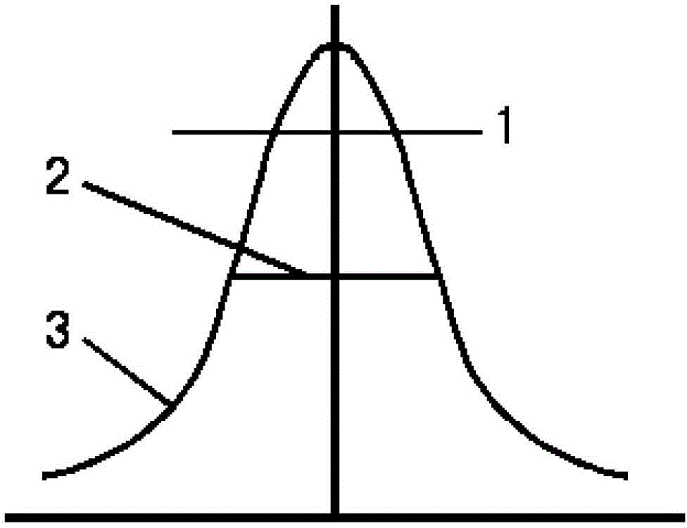
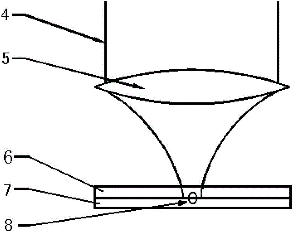
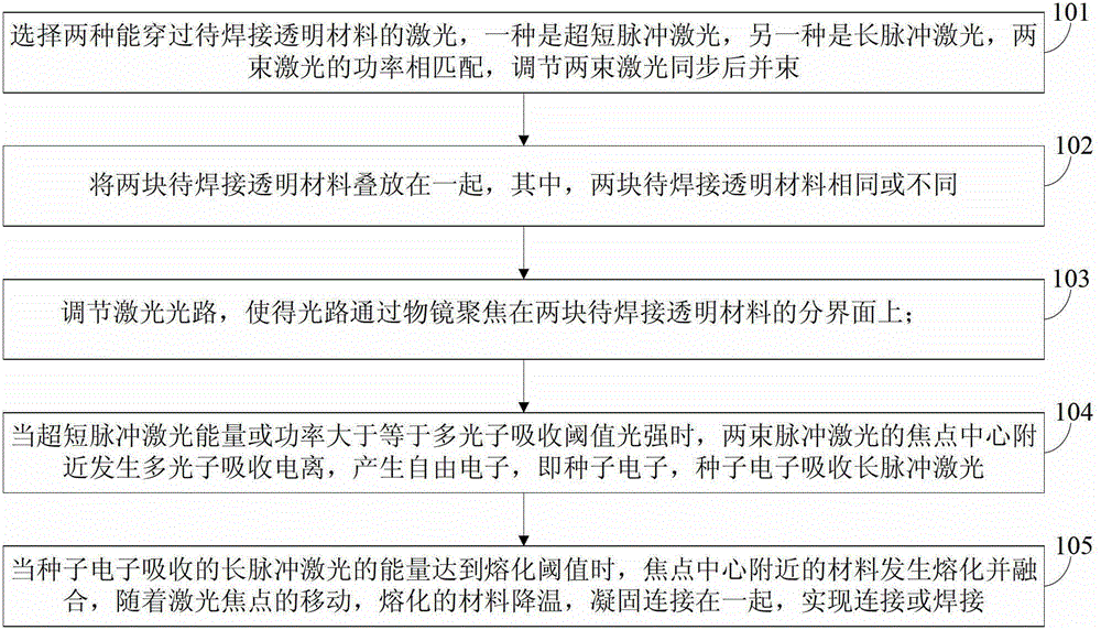
[0023] In order to reduce costs and improve welding efficiency, an embodiment of the present invention provides a method for welding transparent materials, see figure 1 , figure 2 with image 3 , the method includes the following steps:

[0024] 101: Choose two lasers that can penetrate the transparent material to be welded, one is an ultrashort pulse laser, the other is a long pulse laser, the power of the two laser beams matches, and the two laser beams are adjusted to be synchronized and beamed together;

[0025] In actual implementation, the power of the two lasers needs to be determined according to the materials in practical applications. Ultrashort pulse lasers usually choose a pulse width of femtosecond or picosecond order o...


PUM

PropertyMeasurementUnit
laser radiation transmissionaaaaaaaaaa

Abstract

A method for welding transparent material includes: selecting two types of laser capable of transmitting the transparent material to be welded, one being ultrashort pulse laser and the other being long pulse laser, and synchronizing the two laser beams and combining the beams; stacking two blocks of transparent material to be welded; allowing the laser beams to focus on an interface of the two blocks of transparent material to be welded through an objective lens; when the energy (or power) of the ultrashort pulse laser is larger than or equal to multiphoton absorption threshold intensity, allowing occurrence of multiphoton absorption (ionization) near the focus center (of the two pulse laser beams) to generate free electrons which are seed electrons capable of absorbing the long pulse laser; and when the energy of the long pulse laser (absorbed by the seed electrons) reaches a melting threshold of the material to be welded, and allowing the material near the focus center to melt and fuse and connect together so as to achieve connecting or welding. Compared with the welding method using the ultrashort pulse laser only, the method has lowered cost and improved welding efficiency. Welding of the transparent material is achieved.

Description

technical field [0001] The invention relates to welding of materials, in particular to a method for welding transparent materials. Background technique [0002] Transparent materials are widely used in optics, electronic devices, biomedicine and micro-opto-electro-mechanical systems (MOEMS). However, the problem of connecting transparent materials has not been well resolved. Now chemical adhesives or intermediate layers are mainly used. Such connections cannot guarantee good mechanical properties, good thermal and chemical stability. [0003] Recently, an ultrashort pulse laser welding method has been proposed. The ultrashort pulse laser has a very high peak power, which can realize multi-photon absorption (ionization), that is, the laser beam can penetrate the surface of the material, and the energy flux density at the laser focus can reach or exceed the multi-photon absorption (ionization) threshold, and the material will melt , if the laser is focused on the interface b...

Claims


Application Information

Patent Timeline
Patent Type & Authority Applications(China)
IPC IPC(8): B23K26/20B23K26/21
Inventor 贾威于俭刘博文胡明烈柴路王清月
Owner TIANJIN UNIV
Learn More