Hybrid drive apparatus

A driving device and hybrid technology, applied in the direction of power devices, hybrid vehicles, pneumatic power devices, etc., can solve the problems of high relative speed, influence of transmission efficiency of hybrid drive devices, increase of rotation difference, etc., and achieve effective transmission , effective regeneration, power transmission loss suppression effect

Inactive Publication Date: 2013-02-06
HONDA MOTOR CO LTD
View PDF6 Cites 39 Cited by
  • Summary
  • Abstract
  • Description
  • Claims
  • Application Information

AI Technical Summary

Problems solved by technology

However, in the planetary gear mechanism of the hybrid drive device configured as described above, the relative speed (rotation difference) between the sun gear and the ring gear is relatively large, so the rotation difference (slippage) of the friction material in the state where the clutch is not engaged speed) increase
Therefore, the friction loss in the clutch has an influence on the transmission efficiency of the hybrid drive device.

Method used


Image

  • Hybrid drive apparatus
  • Hybrid drive apparatus
  • Hybrid drive apparatus

Examples


no. 1 Embodiment approach

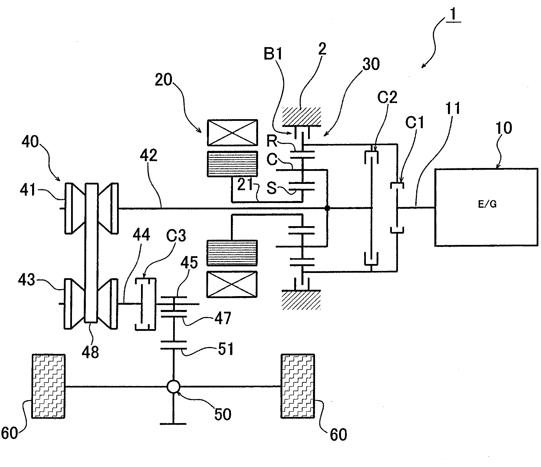
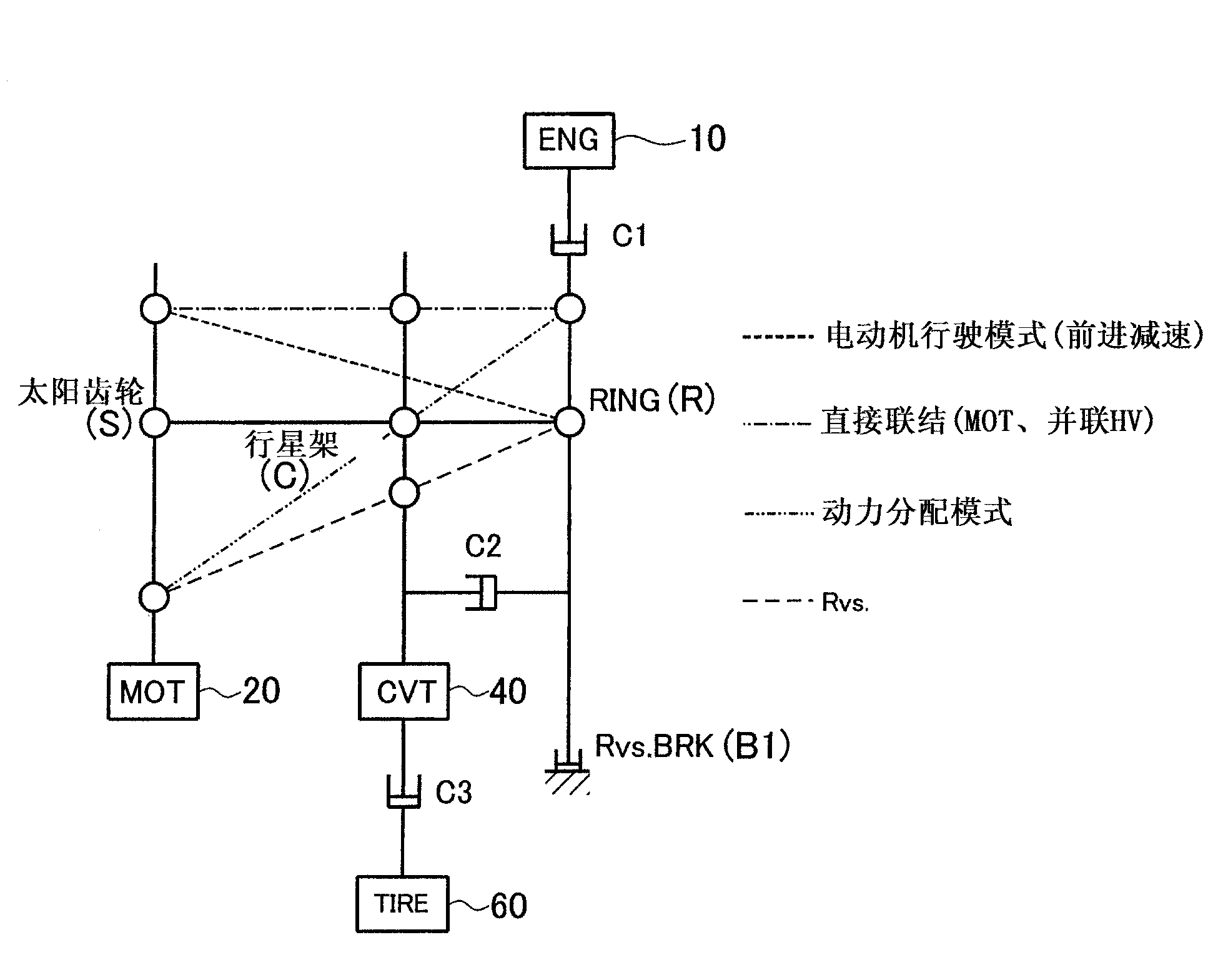
[0054] figure 1 It is a schematic diagram showing the configuration of the hybrid drive device according to the first embodiment of the present invention. also, figure 2 It is a nomographic diagram (velocity diagram) showing the velocity relationship of each element of the planetary gear mechanism included in the hybrid drive device. figure 1 The illustrated hybrid drive device 1 is configured to include: an engine 10 that generates power by burning fuel; a motor generator 20 that functions as an electric motor and a generator; a single-planetary planetary gear mechanism (planetary gear ) 30 having three elements of the sun gear S, the ring gear R, and the carrier C;

[0055] The output shaft (rotation shaft) 21 of the motor generator 20 is connected to the sun gear S of the planetary gear mechanism 30 , and the input shaft (first rotation shaft) 42 connected to the drive pulley 41 of the continuously variable transmission mechanism 40 is connected to the carrier C. In add...

no. 2 Embodiment approach

[0077]Next, a second embodiment of the present invention will be described. In addition, in the description of the second embodiment and the corresponding drawings, the same reference numerals are assigned to the same or corresponding structural parts as those of the first embodiment, and detailed description of these parts will be omitted below. In addition, matters other than the matters described below are the same as those of the first embodiment.

[0078] Figure 5 It is a schematic diagram showing the configuration of a hybrid drive device 1 - 2 according to the second embodiment of the present invention. In the hybrid drive device 1 - 2 shown in the figure, it is provided between the sun gear S and the carrier C of the planetary gear mechanism 30 (the output shaft 21 of the motor generator 20 and the input shaft 42 of the continuously variable transmission mechanism 40 between) the additional second clutch C2′ set to replace the figure 1 In the hybrid drive device 1 ...

no. 3 Embodiment approach

[0081] Next, a third embodiment of the present invention will be described. Figure 6 It is a schematic diagram showing the configuration of a hybrid drive device according to a third embodiment of the present invention. In the hybrid drive device 1 - 3 of the third embodiment shown in the figure, another third shaft provided on the input shaft (first rotating shaft) 42 connected to the driving pulley 41 of the continuously variable transmission mechanism 40 is provided. Clutch C3′, to replace the figure 1 In the hybrid drive device 1 of the first embodiment shown, the third clutch C3 is provided on the output shaft (second rotating shaft) 44 connected to the driven pulley 43 of the continuously variable transmission mechanism 40 . Other configurations are the same as those of the hybrid drive device 1 of the first embodiment.

[0082] In the hybrid drive device 1-3 of the present embodiment, the third clutch C3 is provided on the input shaft 42 of the continuously variable ...


PUM


Abstract

A hybrid drive apparatus is provided and enables efficient energy regeneration by the motor generator by separating the power transmission path through which the driving force from the engine is transmitted, from the power transmission path between the motor generator and the drive wheels, and also makes it possible to achieve a variety of driving modes while improving power transmission efficiency. In a hybrid drive apparatus (1) having an engine (10), a motor generator (20), and a planetary gear mechanism (30) in which the output shaft (21) of the motor generator (20) is coupled to a sun gear (S), the output shaft (11) of the engine (10) is coupled to a ring gear (R), and the input shaft (42) of a continuously variable transmission mechanism (40) is coupled to a carrier (C), the hybrid drive apparatus (1) includes a first clutch (C1) that can switch engagement / disengagement between the output shaft (11) of the engine 11 and the ring gear (R), a second clutch (C2) that can switch engagement / disengagement between the carrier (C) and the ring gear (R), and a third clutch (C3) that can switch engagement / disengagement on the input shaft (42) of the transmission mechanism (40).

Description

technical field [0001] The present invention relates to a hybrid drive device including an engine that generates power by combustion of fuel, and a motor generator that functions as an electric motor and a generator. Background technique [0002] Conventionally, for example, as shown in Patent Documents 1 and 2, there is a hybrid drive device for a vehicle that includes an engine that generates power by burning fuel, and a motor generator that functions as an electric motor and a generator. functions; a planetary gear mechanism (planetary gear) that synthesizes and outputs driving force input from the engine and a motor generator; and a speed change mechanism that can change the speed of rotation based on the driving force from the planetary gear mechanism and output it to the drive wheel side. In the hybrid drive device described in Patent Document 1, the output shaft of the engine is connected to the ring gear of the planetary gear, the output shaft of the motor generator...

Claims


Application Information

Patent Timeline
Patent Type & Authority Applications(China)
IPC IPC(8): B60K6/44B60K6/543
CPCY02T10/623B60K6/365Y02T10/6221B60K6/543B60K6/44B60K6/445Y02T10/6243Y02T10/62
Inventor 矢崎徹
Owner HONDA MOTOR CO LTD
Why Eureka
Try Eureka